
Connection rod die cutting device

A connecting rod and die-cutting technology, which is applied in metal processing and other directions, can solve the problems of large cylinders or oil cylinders, burrs, and parts that cannot be cut evenly, and achieve the effects of stable cutting, reduced loss, and uniform force

Inactive Publication Date: 2018-04-24
江阴市汇通包装机械有限公司
View PDF0 Cites 5 Cited by
  • Summary
  • Abstract
  • Description
  • Claims
  • Application Information

AI Technical Summary

Problems solved by technology

[0002] Ordinary die-cutting device The general die-cutting knife is connected by an air cylinder or an oil cylinder to control the opening and closing up and down, but the air cylinder or oil cylinder can only control one point, so it is difficult to ensure that every point of the die-cutting knife is evenly stressed, which may cause As a result, some parts cannot be cut evenly, and there are burrs. At the same time, the force on the cylinder or oil cylinder is relatively large, and it is easy to wear

Method used


Image

  • Connection rod die cutting device
  • Connection rod die cutting device

Examples


Embodiment Construction

[0009] All features disclosed in this specification, or steps in all methods or processes disclosed, may be combined in any manner, except for mutually exclusive features and / or steps.

[0010] Any feature disclosed in this specification (including any appended claims, abstract and drawings), unless expressly stated otherwise, may be replaced by alternative features which are equivalent or serve a similar purpose. That is, unless expressly stated otherwise, each feature is one example only of a series of equivalent or similar features.

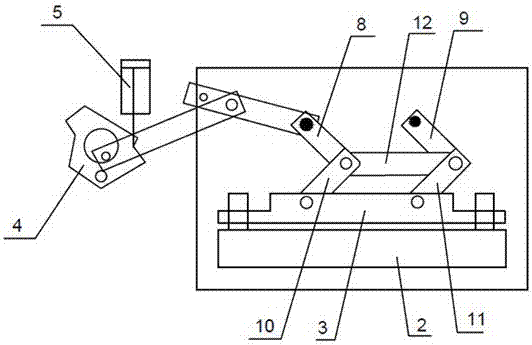
[0011] Such as figure 1 A connecting rod die-cutting device shown includes a frame 1, a lower plate 2 and a die-cutting knife 3, a plurality of positioning pins 13 are uniformly arranged on the lower plate 2, and the die-cutting knife 3 is fitted on the positioning pins 13, The top of the die cutter 3 is connected with a fourth connecting rod 10 and a fifth connecting rod 11 through a pin shaft. The fourth connecting rod 10 and the fifth conn...


PUM


Abstract

The invention discloses a connecting rod die-cutting device, which comprises a frame, a lower plate and a die-cutting knife. A plurality of positioning pins are arranged on the lower plate. The die-cutting knife is fitted on the positioning pins. The connecting rod and the fifth connecting rod, the fourth connecting rod and the fifth connecting rod are respectively connected to the second connecting rod and the third connecting rod, the second connecting rod is connected to the tie rod through the first connecting rod, the tie rod is connected to the special-shaped block, and the special-shaped quick connection cylinder. When the cylinder pulls the special-shaped block, because the special-shaped block has an eccentric structure, the pull rod pulls the first connecting rod to make it press down. Since the top ends of the second connecting rod and the third connecting rod are fixed on the frame, the second connecting rod and the fourth connecting rod The connecting rods are bent, and the third connecting rod and the fifth connecting rod are bent, so that the die-cutter can be pulled up along the positioning pin, and the two points act on the die-cutter at the same time, so that the die-cutter is The force is more uniform, the cutting is stable, and the loss of the cylinder is reduced.

Description

technical field [0001] The invention relates to a connecting rod die-cutting device. Background technique [0002] Ordinary die-cutting device The general die-cutting knife is connected by an air cylinder or an oil cylinder to control the opening and closing up and down, but the air cylinder or oil cylinder can only control one point, so it is difficult to ensure that every point of the die-cutting knife is evenly stressed, which may cause As a result, some parts cannot be cut evenly, and there are burrs. At the same time, the force on the cylinder or oil cylinder is relatively large, and it is easy to wear. Contents of the invention [0003] The invention relates to a connecting rod die-cutting device, which is used to solve the above problems. [0004] In order to achieve this purpose, the structure adopted in the present invention is: a connecting rod die-cutting device, including a frame, a lower plate and a die-cutting knife, a plurality of positioning pins are evenl...

Claims


Application Information

Patent Timeline
IPC IPC(8): B26F1/38B26D5/12B26D5/18
CPCB26F1/38B26D5/12B26D5/18
Inventor 吴卫江吴健
Owner 江阴市汇通包装机械有限公司
Features
  • Generate Ideas
  • Intellectual Property
  • Life Sciences
  • Materials
  • Tech Scout
  • Unparalleled Data Quality
  • Higher Quality Content
  • 60% Fewer Hallucinations
Learn More