Yarn winding device

A winding device and yarn technology, applied in transportation and packaging, conveying filamentous materials, thin material processing, etc., can solve problems such as inability to change pressure

Active Publication Date: 2018-04-24
MURATA MASCH LTD
View PDF11 Cites 4 Cited by
  • Summary
  • Abstract
  • Description
  • Claims
  • Application Information

AI Technical Summary

Problems solved by technology

In other words, it is not possible to change the pressure in the working chamber to an arbitrary value during deceleration

Method used


Image

  • Yarn winding device
  • Yarn winding device
  • Yarn winding device

Examples


Embodiment Construction

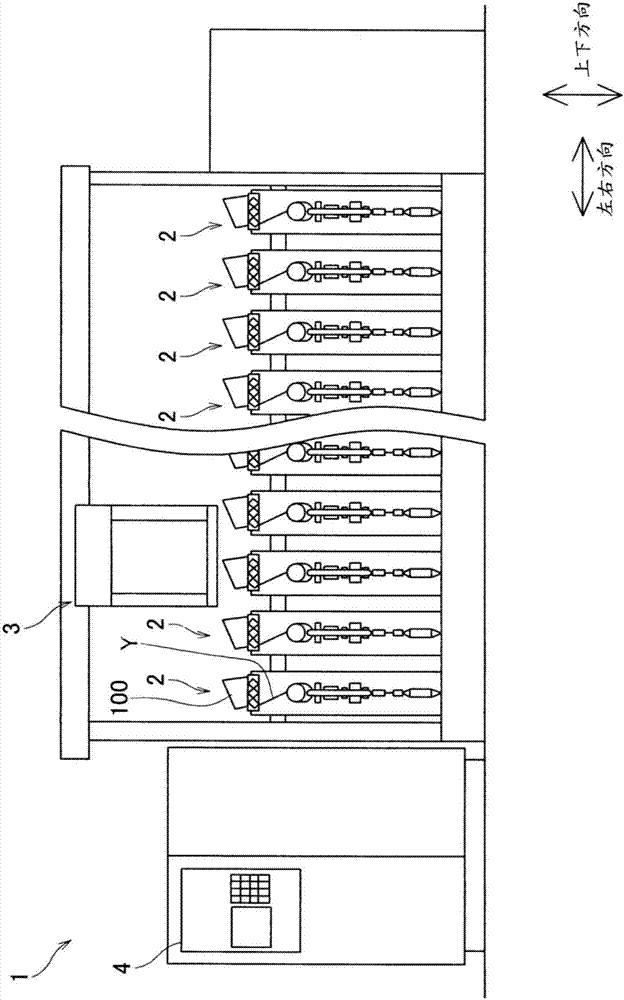
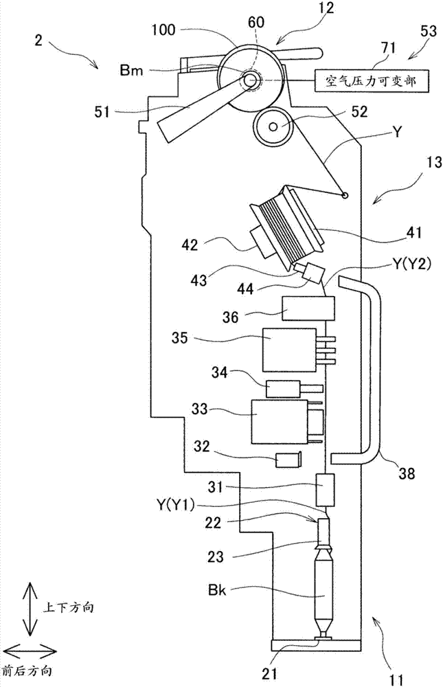
[0044] Next, refer to Figure 1 to Figure 9 Embodiments of the present invention will be described. In addition, if figure 1 As shown, the direction in which the plurality of winding units are arranged is defined as the left-right direction, and the direction in which gravity acts is defined as the vertical direction. In addition, let the direction perpendicular to the left-right direction and the up-down direction be the front-rear direction.

[0045] Brief structure of automatic winder

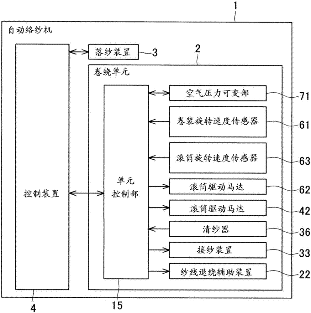
[0046] First, use figure 1 as well as figure 2 A brief configuration of the automatic winder 1 will be described. figure 1 It is a front view of the automatic winder 1 according to this embodiment. figure 2 It is a block diagram showing the electrical configuration of the automatic winder 1 . The automatic winder 1 includes a plurality of winding units 2 (yarn winding devices of the present invention), a doffing device 3, a control device 4, and the like.

[0047] A plurality of wi...


PUM


Abstract

The invention relates to a yarn winding device. The magnitude of the braking force acting on the package can be changed at any moment during the deceleration process of the package. A winding unit includes a braking device that includes a braking shoe that brakes a package, a chamber that operates the braking shoe, and an air pressure changing section that changes a pressure of fluid supplied to the chamber. The air pressure changing section includes a first solenoid valve arranged between a supply port and the chamber, a second solenoid valve arranged between the chamber and an exhaust port,and an air pressure controlling section that opens and closes the solenoid valves independently. When the first solenoid valve is opened and the second solenoid valve is closed, the pressure of the fluid supplied to the chamber increases. When the first solenoid valve is closed and the second solenoid valve is opened, the pressure decreases. The pressure can be maintained at a constant value by closing both the solenoid valves. Accordingly, the pressure can be adjusted at any moment, and the magnitude of the braking force acting on the package can be changed at any moment.

Description

technical field [0001] The present invention relates to yarn winding devices. Background technique [0002] Japanese Patent Application Laid-Open No. 2016-78995 discloses a yarn winding device that winds a yarn supplied from a yarn supplying section around a winding bobbin to form a package. In detail, a configuration including a contact roller that rotates the package while contacting it and a roller drive source that drives the contact roller is shown. Also, a configuration for directly braking the rotation of the package is disclosed. [0003] The above-mentioned yarn winding device includes: a rotary frame that rotates integrally with the winding bobbin, a package brake that brakes the rotary frame by the pressure of compressed air, a solenoid valve that switches supply and stop of compressed air to the package brake, and Control unit for opening and closing the solenoid valve. The package brake has a brake piston that brakes the rotation of the rotary bracket, and a ...

Claims


Application Information

Patent Timeline
Patent Type & Authority Applications(China)
IPC IPC(8): B65H54/42B65H54/02B65H54/48
CPCB65H54/02B65H54/42B65H54/48B65H2403/7252B65H2406/40B65H54/553B65H54/74B65H2701/31
Inventor 阵山达夫
Owner MURATA MASCH LTD
Why Eureka
Try Eureka