Pneumatic jaw clutch

A pneumatic clutch and claw-type technology, which is applied to fluid-driven clutches, clutches, non-mechanical-driven clutches, etc., can solve the problems of poor maintainability and complex structure, and achieve the effect of small size, compact structure and reliable connection.

Active Publication Date: 2018-04-27
BEIJING RES INST OF PRECISE MECHATRONICS CONTROLS
View PDF10 Cites 4 Cited by
  • Summary
  • Abstract
  • Description
  • Claims
  • Application Information

AI Technical Summary

Problems solved by technology

[0003] At present, the valve opening and closing of a ship is controlled by

Method used


Image

  • Pneumatic jaw clutch
  • Pneumatic jaw clutch
  • Pneumatic jaw clutch

Examples


Embodiment Construction

[0027] The jaw type pneumatic clutch provided by the present invention will be further described in detail below in conjunction with the accompanying drawings and specific embodiments.

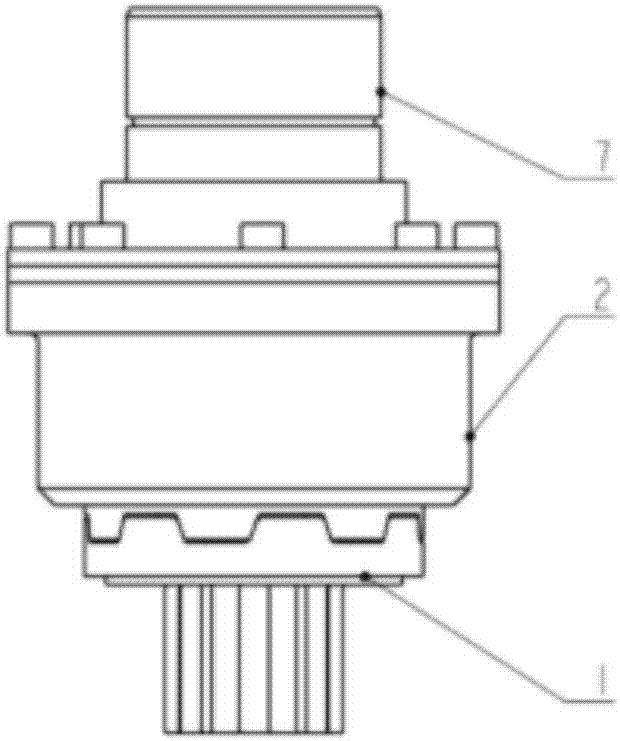
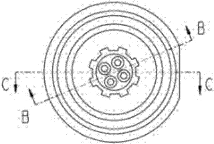
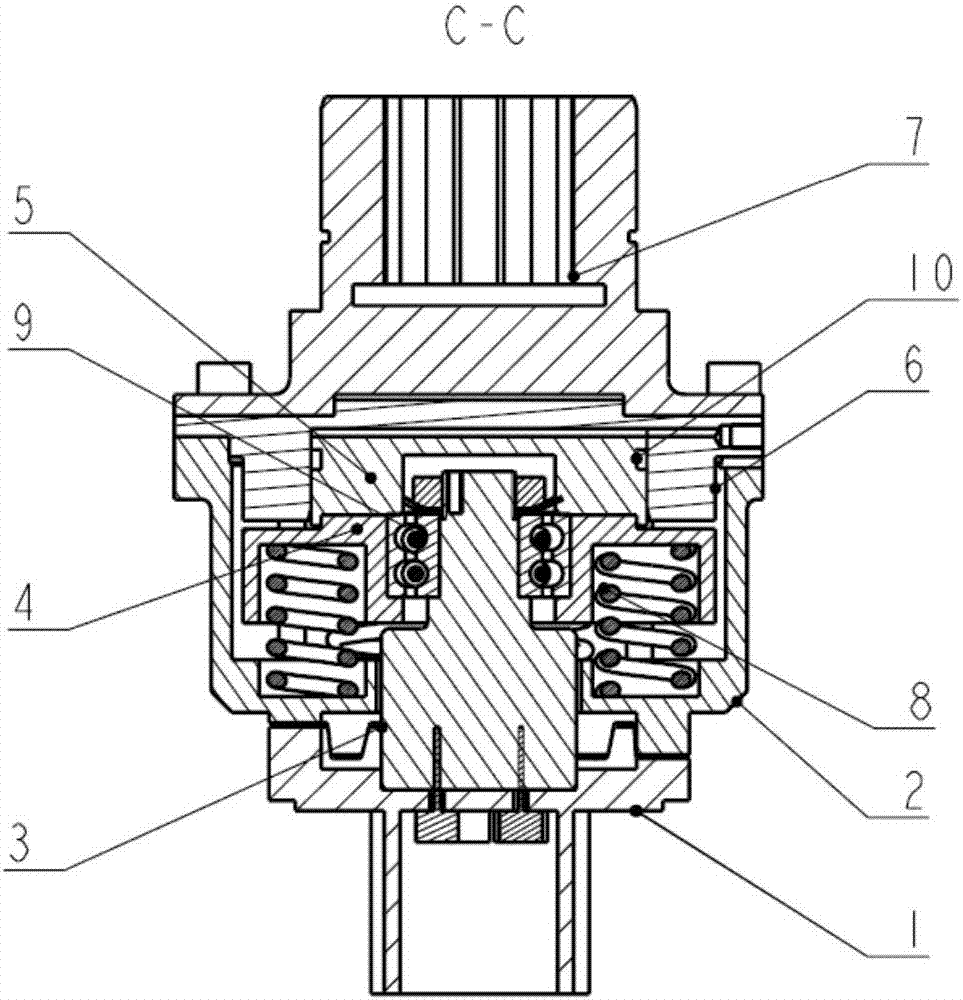
[0028] Such as Figure 1-4 As shown, a jaw type pneumatic clutch includes left half clutch 1, right half clutch 2, rotating shaft 3, spring seat 4, piston 5, cylinder 6, output shaft 7, preload spring 8, double row angular contact bearing 9 , O-ring 10, adjusting screw 11, spring washer 12, anti-rotation screw 13, fastening screw 14, spring washer 2 15, stop washer 16, lock nut 17, fastening screw 2 18;

[0029] Among them: the left half clutch part includes left half clutch 1, rotating shaft 3, double row angular contact ball bearing 9, lock nut 17, brake washer 16, spring seat 4 and piston 5, and the parts are fixedly connected by fastening screws 14;

[0030] The right half clutch part includes the right half clutch 2, the cylinder 6 and the output shaft 7, and the parts are fixedly connec...


PUM


Abstract

The invention belongs to the technical field of electric valve actuators, and in particular, relates to a pneumatic jaw clutch. The pneumatic jaw clutch comprises a left half clutching part and a right half clutching part; the left half clutching part comprises a left half clutch, a rotating shaft, a double-row angular contact ball bearing, a locking nut, a brake gasket, a spring base and a piston; the right half clutching part comprises a right half clutch, a cylinder and an output shaft; the left half clutching part and the right half clutching part are connected through end surface teeth; the end surface teeth adopt a design of self-locking structures; and a pretightening spring is arranged between the left half clutching part and the right half clutching part. The pneumatic jaw clutchachieves a coupling effect to transfer an output torque in normal work, and uses a final energy air source for driving the clutch to open a valve to achieve an emergency function in emergent work.

Description

technical field [0001] The invention belongs to the technical field of electric valve actuators, and in particular relates to a jaw-type pneumatic clutch. Background technique [0002] For ship systems, reliability is undoubtedly the first. The jaw-type pneumatic clutch, as the emergency equipment of the electric valve actuator, is of great significance to improving the safety of the personnel in the boat and the reliability of the equipment. [0003] At present, the valve opening and closing of a ship is controlled by a hydraulic cylinder, which has a complex structure and poor maintainability. For this reason, electric valve actuators are used to replace hydraulic cylinders to control valve opening and closing. In order to improve the reliability of the electric valve actuator, so that it can ensure the normal opening of the controlled valve even in the case of power failure, it is necessary to develop an emergency equipment that can use the last energy source on the shi...

Claims


Application Information

Patent Timeline
IPC IPC(8): F16D25/061
CPCF16D25/061
Inventor 张阳韩旭马德森赵国平陈祖希
Owner BEIJING RES INST OF PRECISE MECHATRONICS CONTROLS
Why Eureka
Try Eureka