
Router mounting bracket

A technology for installing brackets and routers, which is applied in the direction of machines/brackets, supporting machines, digital transmission systems, etc. It can solve the problems of frequent rotation of antennas and signals can only be transmitted forward, so as to ensure the service life and reduce the probability of loosening. The effect of reducing accumulation

Active Publication Date: 2018-04-27
重庆锐正科技有限公司
View PDF5 Cites 5 Cited by
  • Summary
  • Abstract
  • Description
  • Claims
  • Application Information

AI Technical Summary

Problems solved by technology

[0004] The present invention intends to provide a router mounting bracket to solve the problem that the user needs to frequently rotate the antenna when surfing the Internet at different locations because the signal of the directional antenna of the router can only be transmitted forward

Method used


Image

  • Router mounting bracket
  • Router mounting bracket
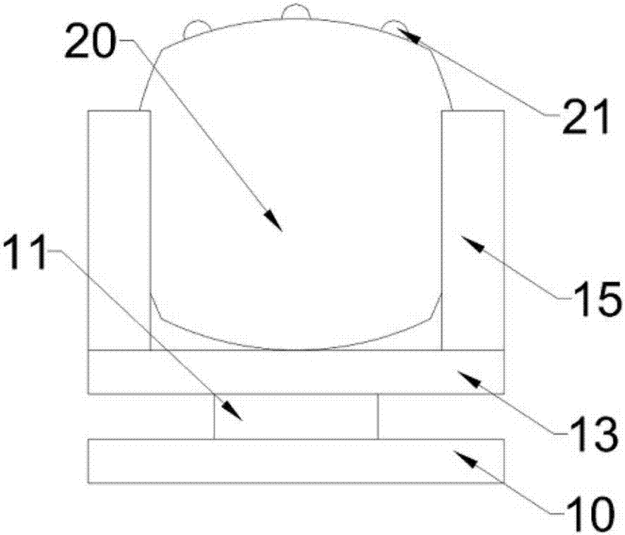
  • Router mounting bracket

Examples


Embodiment Construction

[0022] Further detailed explanation through specific implementation mode below:

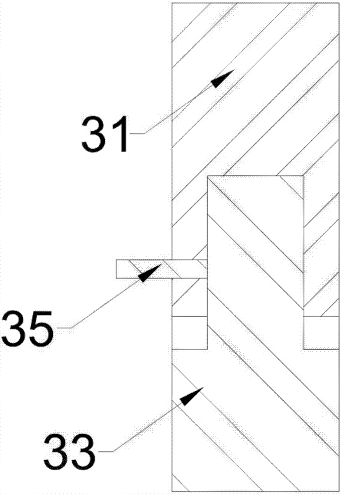
[0023] The reference signs in the accompanying drawings include: base 10 , support rod 11 , support seat 13 , limit rod 15 , router 20 , antenna 21 , fixed end 31 , rotating end 33 , and fixing member 35 .

[0024] Such as figure 1 The shown router mounting bracket includes a base 10, the base 10 is connected with a rotatable support base 13, the bottom surface of the support base 13 is provided with a network cable hole, and the two sides of the support base 13 are provided with limit rods 15, and the limit rod 15 is set There is a limiting groove for vertically placing the router 20, and because the router 20 generates heat during use, the limiting rod 15 is also provided with cooling holes, and part of the heat on the router 20 is dissipated through the cooling holes, ensuring Normal use of the router 20.

[0025] It also includes a drive module, which is used to drive the support base 13 to...


PUM


Abstract

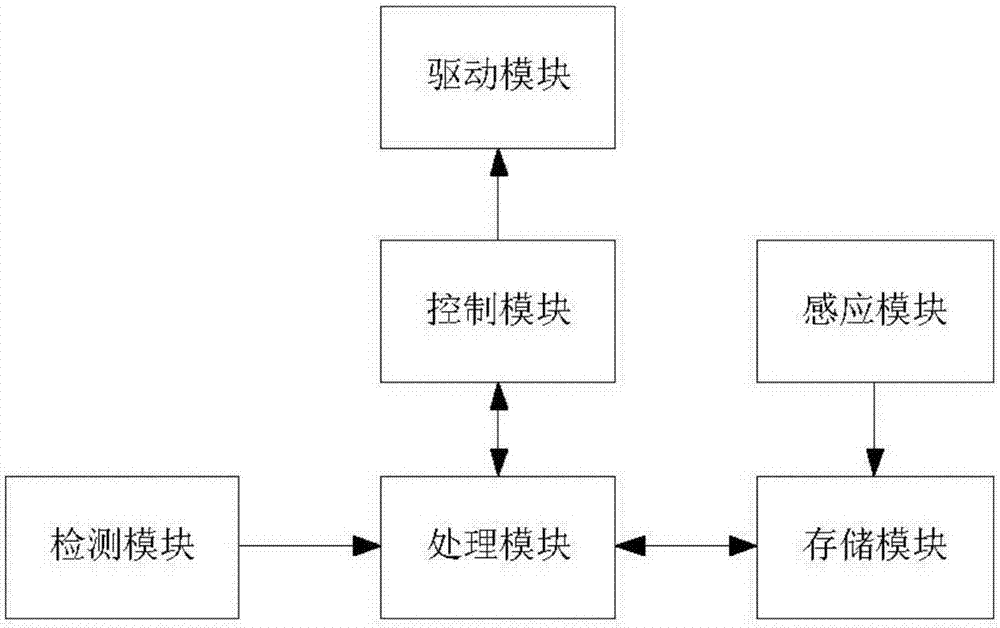
The invention relates to the field of mounting equipment for mobile communication equipment and provides a router mounting bracket for solving the problems that signals of a bidirectional antenna of arouter are transmitted forwards only and a user needs to frequently rotate the antenna when surfing the Internet at different positions. The router mounting bracket comprises a pedestal, a driving module, a sensing module, a storage module, a detection module, a processing module and a control module, wherein the pedestal is connected with a rotatable supporting seat; the driving module is used for driving the supporting seat to rotate; the sensing module is used for sending position sensation information when a user is in a sensing region; the storage module is used for storing the positionsensation information; the detection module is used for detecting a signal accessing to the router and sending a start signal after detecting that the signal accesses to the router; the processing module is used for processing the current position sensation information and the previous position sensation information stored in the storage module after receiving the start signal and generating angleinformation of the rotation required by the supporting seat; and the control module is used for controlling the driving module to rotate a corresponding angle according to the angle information.

Description

technical field [0001] The invention relates to the field of installation equipment for mobile communication equipment, in particular to a router installation bracket. Background technique [0002] A router is a device connected to various LANs and WANs in the Internet. It will automatically select and set routes according to the channel conditions, and send signals in the order of the best path. The router is composed of the main body of the router and the antenna installed on the main body of the router. The function of the antenna is to transmit and receive electromagnetic wave signals, and the antenna has different radiation or receiving capabilities for different directions in space, that is, the antenna is directional. There are two types of antennas: omnidirectional and directional. As the name implies, the omnidirectional antenna will transmit signals in all directions, and the signals can be received from the front, rear, left, and right sides. The directional ante...

Claims


Application Information

Patent Timeline
Patent Type & Authority Applications(China)
IPC IPC(8): F16M11/06F16M11/16H04L12/771H04L45/60
CPCH04L45/60F16M11/06F16M11/16
Inventor 李治
Owner 重庆锐正科技有限公司
Learn More