
Device for achieving water shortage detection function in steam equipment

A technology of steam equipment and functions, applied in the direction of non-electric variable control, instruments, control/regulation systems, etc., can solve the problems of shortening the service life of water equipment, low sensitivity of water shortage detection results, and reduced safety of equipment use, so as to benefit Effects of maintenance and replacement, improvement of safety in use, and prevention of equipment failure

Pending Publication Date: 2018-04-27
NINGBO HAOJIA ELECTRICAL APPLIANCES CO LTD
View PDF0 Cites 0 Cited by
  • Summary
  • Abstract
  • Description
  • Claims
  • Application Information

AI Technical Summary

Problems solved by technology

[0003] Traditionally, the water shortage detection device on the water equipment includes the following two types. First, a floating steel reed tube structure is installed in the water tank. However, due to the limitation of the floating steel reed tube structure, the installation process in the water tank is complicated and the installation is extremely inconvenient. , the production process is slow, and it is not conducive to the later maintenance and replacement; second, the electrode structure is used, and the electrode structure is installed in the waterway or the water tank. When conducting electricity through water, there are potential safety hazards, which can easily lead to safety accidents, and the sensitivity of the water shortage detection results of this electrode structure is low, which is prone to misjudgment, resulting in a decrease in the safety of the equipment, resulting in equipment failure, shortening the Service life of water equipment

Method used


Image

  • Device for achieving water shortage detection function in steam equipment
  • Device for achieving water shortage detection function in steam equipment
  • Device for achieving water shortage detection function in steam equipment

Examples


Embodiment Construction

[0017] In order to make it easy to understand the technical means, creative features, goals and effects achieved by the present invention, the following examples are combined with the appended figure 1 To attach Figure 4 The technical solutions provided by the present invention are described in detail, but the following content is not intended as a limitation of the present invention.

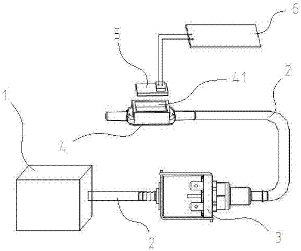
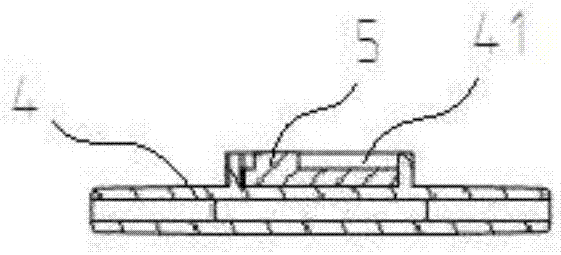
[0018] figure 1 It is a structural diagram of an embodiment of a device for detecting water shortage in steam equipment according to the present invention; figure 2 It is a structural diagram of another arrangement position of the water tank in a preferred embodiment of the present invention; image 3 It is an installation cross-sectional view of a capacitive sensor and a water tank according to a preferred embodiment of the present invention. like figure 1 , figure 2 as well as image 3 As shown, the device for detecting water shortage in steam equipment provided by this embodiment in...


PUM


Abstract

The invention provides a device for achieving a water shortage detection function in steam equipment, which belongs to the technical field of water equipment. A device for achieving a water shortage detection function in steam equipment includes a water pump connected to a water tank through a water pipe. The water pump is also connected with the water pipe. A water sink is arranged on part of thewater pipe. A capacitive sensor is arranged on the outer wall of the water sink or the water tank, and the capacitive sensor is electrically connected to a controller. The controller is electricallyconnected to the water pump. The capacitive sensor is set to detect the volume of water and realize water shortage detection. The device not only costs low, but also has high detection sensitivity. False alarm can be prevented. Water equipment can be prevented from working without water, equipment failure can be prevented, and the service life of equipment can be prolonged. Moreover, the capacitive sensor does not directly contact water, so that higher safety is guaranteed. The capacitive sensor is easy to install, which is conducive to the maintenance and replacement in the later stage and isconducive to the development of enterprises.

Description

technical field [0001] The invention relates to the technical field of water equipment, in particular to a device for detecting water shortage in steam equipment. Background technique [0002] For water equipment, it is the key to improve the safety of water equipment and prolong its service life to detect whether there is water shortage in the equipment more accurately and timely. Therefore, water shortage detection devices are often installed on water equipment. [0003] Traditionally, the water shortage detection device on the water equipment includes the following two types. First, a floating steel reed tube structure is installed in the water tank. However, due to the limitation of the floating steel reed tube structure, the installation process in the water tank is complicated and the installation is extremely inconvenient. , the production process is slow, and it is not conducive to the later maintenance and replacement; second, the electrode structure is used, and th...

Claims


Application Information

Patent Timeline
IPC IPC(8): G05D9/12
CPCG05D9/12
Inventor 赵焕锋李永波
Owner NINGBO HAOJIA ELECTRICAL APPLIANCES CO LTD
Learn More