Cryopreserved box storage tank

A technology of cryopreservation boxes and storage tanks, applied in the direction of packaging objects under special gas conditions, biological packaging, packaging, etc., to achieve the effects of reducing economic losses, improving quality, and ensuring quality

Pending Publication Date: 2018-05-01
SHANGHAI ORIGINCELL BIOLOGICAL CRYO EQUIP CO LTD
View PDF0 Cites 18 Cited by
  • Summary
  • Abstract
  • Description
  • Claims
  • Application Information

AI Technical Summary

Problems solved by technology

[0005] The object of the present invention is to provide a storage tank for cryopreservation boxes, which solves the problem of automatic integrated storage and retrieval of cryopreservation boxes, and at the same time realizes the automatic lowering of the cryopreservation boxes, keeps a relatively low position, and keeps the temperature of the cryopreservation boxes relatively low. Low, improve the quality of biological samples in the freezer boxes, improve the efficiency of selecting freezer boxes, and reduce potential safety hazards

Method used


Image

  • Cryopreserved box storage tank
  • Cryopreserved box storage tank
  • Cryopreserved box storage tank

Examples


Embodiment Construction

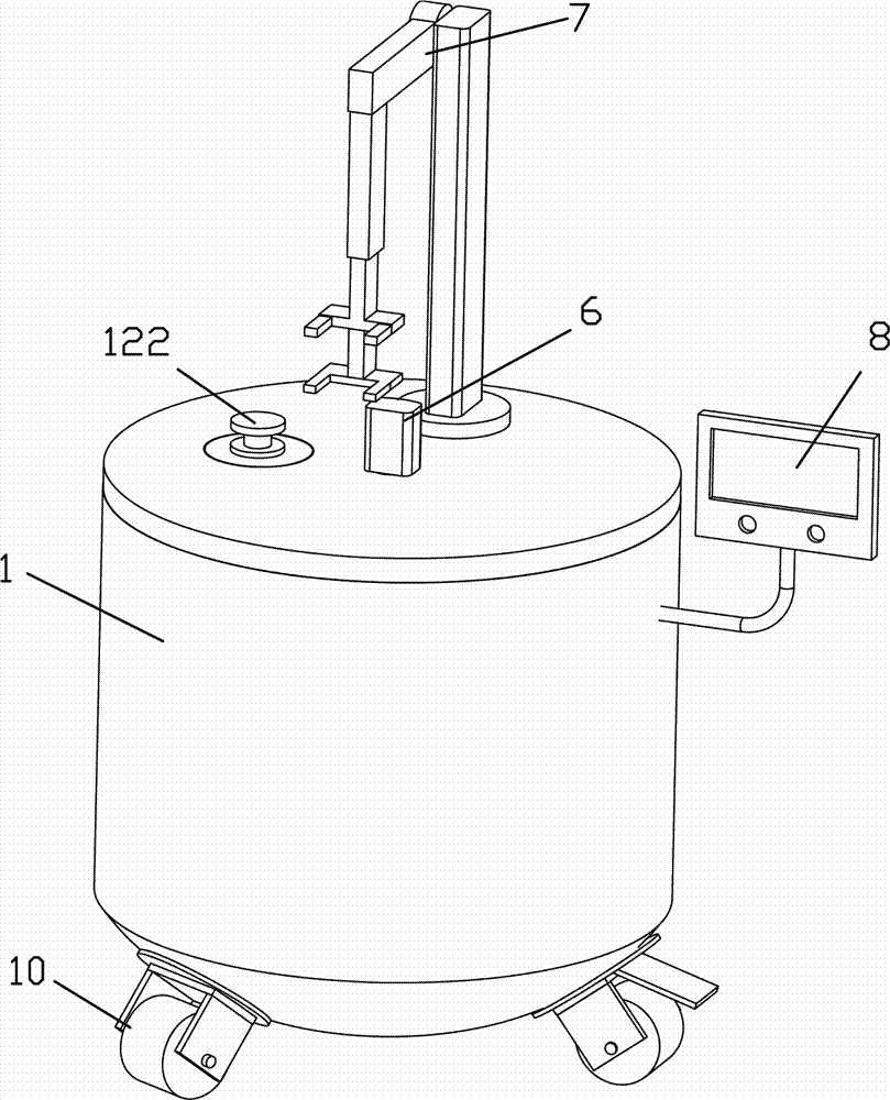
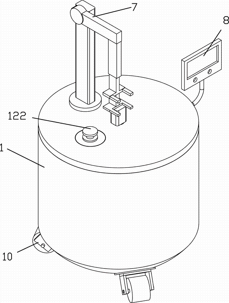
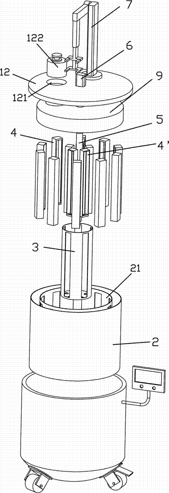
[0037] see Figure 1 to Figure 9 , a kind of freezing box storage tank of the present invention, it comprises:

[0038] The body 1 includes a tank body 11 with an open upper end and a tank cover 12;

[0039] The outer ring drum 2 has an open upper end and is arranged in the main body tank 11; an annular fixing plate 21 is arranged in the outer ring drum 2 along the inner wall circumference to form an annular accommodation space in the outer ring drum 2 200: On the fixed plate 21, several strip holes 211 are evenly spaced along the circumferential direction, and the bottom of the outer ring drum 2 corresponding to the annular accommodation space of the strip holes 211 is provided with several first through holes 22 that can introduce cold air ;

[0040] The inner ring drum 3 is open at its upper end and is arranged in the center of the outer ring drum 2 . The side wall of the inner ring drum 3 is evenly spaced along the circumferential direction with a plurality of strip-shap...


PUM


Abstract

The invention relates to a cryopreserved box storage tank, which comprises a main body, an outer ring drum, an inner ring drum, a plurality of storage racks, a plurality of cryopreserved boxes, a rotary shaft, a motor, a mechanical arm and a controller. The main body comprises a tank body and a tank cover; the outer ring drum is opened at the upper end and is arranged in the tank body; an annularfixing plate is arranged in the outer ring drum along a circumferential direction of an inner wall; strip-shaped holes are uniformly formed in the fixing plate at intervals along a circumferential direction; the inner ring drum is opened at the upper end and is arranged in the center in the outer ring drum; strip-shaped holes are formed in a side wall of the inner ring drum at intervals along a circumferential direction; one side surface of each storage rack is opened; through holes are formed in the bottom parts of the storage racks; the storage racks are vertically arranged in the outer ringdrum and the inner ring drum; the opening sides of the storage racks correspond to the strip-shaped holes; an access hole and a plug body are arranged in an access space at a position, correspondingto a part between the two circles of storage racks, on a cover body; the cryopreserved boxes are stacked in the storage racks; the rotary shaft is arranged in the center of the main body in a penetrating way; the upper end of the rotary shaft stretches out from the center of the tank cover; the lower end of the rotary shaft penetrates through the centers of the inner ring drum and the outer ring drum and stretches out from the center of the bottom part of the tank body; the motor is arranged on the tank cover of the main body; an output shaft of the motor is connected with the rotary shaft; the mechanical arm is arranged on the tank cover of the main body; the controller is arranged on one side of the tank body of the main body; and the motor and the mechanical arm are electrically connected with the controller.

Description

technical field [0001] The invention belongs to the field of storage of biological samples, in particular to a storage tank of a cryopreservation box. Background technique [0002] The deep cryogenic biological sample bank is an important basic equipment for research in the fields of medicine and biology. The low temperature storage of liquid nitrogen can keep biological tissues such as blood, stem cells and immune cells alive for a long time. [0003] At present, the liquid nitrogen storage tank is a manual structure. When selecting the cryopreservation tube, the operator needs to open the tank cover, reach into the tank body and take out the entire cryopreservation box, then pick out a single cryopreservation tube, and store it in the cryopreservation tube. During the process, it is also necessary to take out the entire cryopreservation tray and store it in a single cryopreservation tube. With this access method, the operation efficiency is very low and the error rate is h...

Claims


Application Information

Patent Timeline
Patent Type & Authority Applications(China)
IPC IPC(8): B65D81/20B65D25/52B65D85/50
CPCB65D81/2076B65D25/52B65D85/50
Inventor 瞿建国罗沉王建信
Owner SHANGHAI ORIGINCELL BIOLOGICAL CRYO EQUIP CO LTD
Why Eureka
Try Eureka