Efficient wool removing equipment for textiles

A textile, high-efficiency technology, applied in the direction of floating yarn, etc., can solve the problems of generating a lot of dust, slow shaving, affecting human health, etc.

Active Publication Date: 2018-05-01
上海雁峰纺织品有限公司
View PDF5 Cites 9 Cited by
  • Summary
  • Abstract
  • Description
  • Claims
  • Application Information

AI Technical Summary

Problems solved by technology

[0007] In order to overcome many shaving machines, the efficiency of hair removal is low, the speed of shaving is slow, and a lot of dust will be generated during shaving, which will affect the health of the human bod

Method used


Image

  • Efficient wool removing equipment for textiles
  • Efficient wool removing equipment for textiles
  • Efficient wool removing equipment for textiles

Examples


Embodiment 1

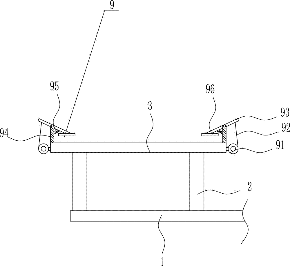
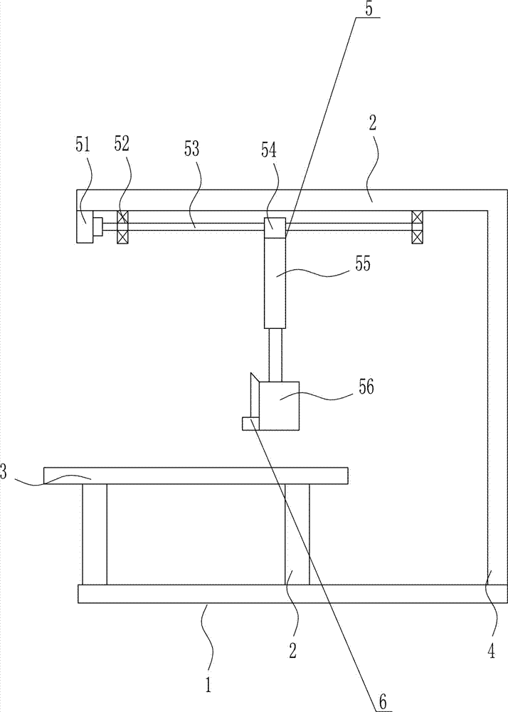
[0037] A kind of high-efficiency hair removal equipment for textiles, such as Figure 1-5 As shown, it includes a base plate 1, a support rod 2, a placement plate 3, an L-shaped plate 4, a moving mechanism 5 and a depilation mechanism 6. The left side of the base plate 1 top is provided with a left-right symmetrical support rod 2, and the support rod 2 is provided with Place plate 3 is arranged, the right side of base plate 1 top is provided with L-shaped plate 4, the bottom of upper L-shaped plate 4 is provided with moving mechanism 5, and the below of moving mechanism 5 is provided with depilatory mechanism 6.

Embodiment 2

[0039] A kind of high-efficiency hair removal equipment for textiles, such as Figure 1-5 As shown, it includes a base plate 1, a support rod 2, a placement plate 3, an L-shaped plate 4, a moving mechanism 5 and a depilation mechanism 6. The left side of the base plate 1 top is provided with a left-right symmetrical support rod 2, and the support rod 2 is provided with Place plate 3 is arranged, the right side of base plate 1 top is provided with L-shaped plate 4, the bottom of upper L-shaped plate 4 is provided with moving mechanism 5, and the below of moving mechanism 5 is provided with depilatory mechanism 6.

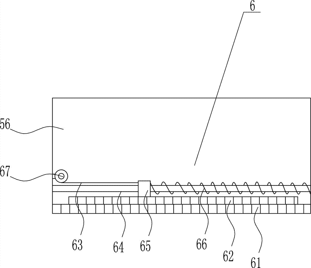
[0040] The moving mechanism 5 includes a motor 51, a first bearing seat 52, a screw rod 53, a nut 54, an electric push rod 55 and a frame body 56, the left side of the top of the L-shaped plate 4 is provided with a motor 51, and the top of the L-shaped plate 4 is provided with a Left-right symmetrical first bearing seat 52, motor 51 is positioned at the left side of ...

Embodiment 3

[0042] A kind of high-efficiency hair removal equipment for textiles, such as Figure 1-5 As shown, it includes a base plate 1, a support rod 2, a placement plate 3, an L-shaped plate 4, a moving mechanism 5 and a depilation mechanism 6. The left side of the base plate 1 top is provided with a left-right symmetrical support rod 2, and the support rod 2 is provided with Place plate 3 is arranged, the right side of base plate 1 top is provided with L-shaped plate 4, the bottom of upper L-shaped plate 4 is provided with moving mechanism 5, and the below of moving mechanism 5 is provided with depilatory mechanism 6.

[0043] The moving mechanism 5 includes a motor 51, a first bearing seat 52, a screw rod 53, a nut 54, an electric push rod 55 and a frame body 56, the left side of the top of the L-shaped plate 4 is provided with a motor 51, and the top of the L-shaped plate 4 is provided with a Left-right symmetrical first bearing seat 52, motor 51 is positioned at the left side of ...


PUM


Abstract

The invention relates to efficient wool removing equipment and particularly relates to efficient wool removing equipment for textiles. A technical problem to be solved by the invention is to provide the efficient wool removing equipment for the textiles. The efficient wool removing equipment is high in wool removing efficiency, high in wool removing speed, and dust can be cleaned during wool removing. The efficient wool removing equipment for the textiles, provided by the invention, comprises a bottom plate and the like, wherein supporting rods which are of bilateral symmetry are arranged at the left side of the top of the bottom plate, a placement plate is arranged on the supporting rods, L-shaped plates are arranged at the right side of the top of the bottom plate, a moving mechanism isarranged at the bottom of the upper L-shaped plate, and an wool removing mechanism is arranged below the moving mechanism. According to the efficient wool removing equipment for the textiles, the effects of being high in wool removing efficiency and high in wool removing speed and cleaning the dust during wool removing are achieved; the textiles are unhaired through firstly, placing the textiles on the placement plate, then, fixing the textiles by a fixing mechanism, then, starting up the moving mechanism, moving the wool removing mechanism to a proper position, and meanwhile, a dust suction mechanism is turned on to clean out generated dust.

Description

technical field [0001] The invention relates to a high-efficiency hair removal device, in particular to a high-efficiency hair removal device for textiles. Background technique [0002] Textile is a product made of textile fibers through processing and weaving. It is divided into two categories: woven fabrics and knitted fabrics. China is one of the earliest countries in the world to produce textiles. The main production areas are Puyuan, Zhejiang Kongkong, Qinghe, Hebei and other places. . [0003] The correct stacking method for textiles is to choose one that is conducive to ventilation and fire prevention. Cotton fabrics are best placed in a well-ventilated place, such as the place closest to the door or window. One row, the second layer is placed vertically, the number must be the same as the bottom, the third layer is still horizontally laid out, the number is the same, and so on. [0004] Clothes pilling is caused by the surface of the fabric rubbing against each oth...

Claims


Application Information

Patent Timeline
IPC IPC(8): D06C13/06
CPCD06C13/06
Inventor 俞虹雷铭张厚忠
Owner 上海雁峰纺织品有限公司
Why Eureka
Try Eureka