U-shaped wall base and bottom plate dynamic and static separation bearing type lining structure with water delivering function

A dynamic and static separation, U-shaped technology, used in wellbore lining, tunnel lining, drainage, etc., can solve the problems of cracking and damage of the tunnel bottom structure, and achieve the effect of clear force, saving masonry, and overcoming the difficult control of excavation curvature.

Pending Publication Date: 2018-05-01
CHINA RAILWAY ERYUAN ENG GRP CO LTD
View PDF7 Cites 3 Cited by
  • Summary
  • Abstract
  • Description
  • Claims
  • Application Information

AI Technical Summary

Problems solved by technology

[0011] The technical problem to be solved by the present invention is to provide a U-shaped wall base and bottom plate dynamic and static separation load-bearing lining structure with the function of water delivery. By transforming the traditional tunnel lining tunnel bottom structure, the stress form and drainage of the tunnel bottom structure can be changed. The system eliminates the effect of groundwater on the bottom structure of the tunnel lining, effectively solves the problem of uplift deformation of the tunnel arch or cracking and damage of the tunnel bottom structure in karst or groundwater-developed areas, and ensures the stability and safety of tunnel construction and operation

Method used


Image

  • U-shaped wall base and bottom plate dynamic and static separation bearing type lining structure with water delivering function
  • U-shaped wall base and bottom plate dynamic and static separation bearing type lining structure with water delivering function

Examples


Embodiment Construction

[0026] The present invention will be described in detail below in conjunction with the accompanying drawings and embodiments.

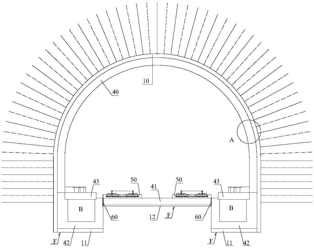
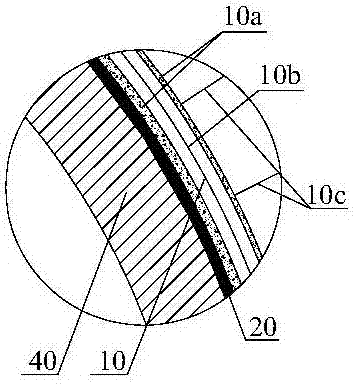
[0027] refer to figure 1 , the U-shaped wall foundation with water delivery function of the present invention and the dynamic and static separation load-bearing lining structure of the base plate include the primary support structure 10 of the arch wall, the secondary lining structure 40 of the arch wall and the waterproof layer 20 in the range of the arch wall. Deep grooves are excavated on both lateral sides of the bottom of the tunnel to form a convex tunnel bottom excavation surface F, and a U-shaped wall foundation structure 42 with a groove-shaped cavity B is arranged in the deep groove, and the outer top of the U-shaped wall foundation structure 42 is connected to the The bottom of the side walls on both sides of the arch wall secondary lining structure 40 is fixed, and the U-shaped wall foundation structure 42 is used as the load-bearing struc...


PUM


Abstract

The invention discloses a U-shaped wall base and bottom plate dynamic and static separation bearing type lining structure with a water delivering function in order to eliminate the effect of groundwater on a bottom structure of a tunnel lining, the problems of floating deformation of a tunnel inverted arch and cracking damage of the tunnel bottom structure in a karst or groundwater development area are effectively solved, and the stability and safety of tunnel construction and operation are guaranteed. Deep grooves are excavated in the two transverse sides of the bottom of a tunnel to form inverted-T-shaped tunnel bottom excavation faces; U-shaped wall base construction bodies with groove-shaped cavities are arranged in the deep grooves; the U-shaped wall base construction bodies are fixedly connected with the wall bottoms of the two side edges of arch wall secondary lining structures; and the U-shaped wall base construction bodies serve as bearing structures of the arch wall secondarylining structures and longitudinal drainage channels of the tunnel. Bottom plates are arranged in the positions, above the middles of the inverted-T-shaped tunnel bottom excavation faces, between theU-shaped wall base construction bodies on the two sides, and road beds are fixedly arranged on the bottom plates; settlement seams are arranged in the connecting positions of the two transverse endsof the bottom plates and the U-shaped wall base construction bodies on the two sides, so that a surrounding rock load transmitted by the arch wall secondary lining structures is separated from a trainload transmitted by the road beds.

Description

technical field [0001] The invention relates to a tunnel lining structure, in particular to a tunnel lining structure used in areas with developed groundwater, areas with irregular groundwater affected by seasons or karst areas. Background technique [0002] With the rapid development of high-speed railway construction, especially large-scale construction in southwest mountainous areas, on the one hand, due to the extensive distribution of limestone stratum; The constraints of the karst tunnels lead to a rapid increase in the scale (number and length) of karst tunnels. Due to the complexity, diversity and irregularity of the development of karst and karst water, the risks of building large karst tunnels, especially their operation, are getting higher and higher. In recent years, several water hazards such as ballastless ballast bed deformation, inverted arch and filling uplift have occurred during the operation of Yiwan, Shanghai-Kunming, Guiguang and other high-speed railw...

Claims


Application Information

Patent Timeline
Patent Type & Authority Applications(China)
IPC IPC(8): E21D11/00E21D11/10E21D11/38E21F16/02
CPCE21D11/003E21D11/10E21D11/38E21F16/02
Inventor 陶伟明卿伟宸钟昌桂林本涛张磊王芳李泽龙朱勇郑伟张慧玲孟祥磊高强
Owner CHINA RAILWAY ERYUAN ENG GRP CO LTD
Why Eureka
Try Eureka