Dual-hole hollow rectangular section bearing cutting type arched tunnel lining structure and separation drainage system

A technology of rectangular section and drainage system, applied in the direction of tunnel lining, tunnel, drainage, etc., can solve problems such as cracking and damage, and achieve the effect of controlling settlement and deformation, reducing engineering construction investment, and achieving significant economic benefits.

Pending Publication Date: 2018-04-13
CHINA RAILWAY ERYUAN ENG GRP CO LTD
View PDF8 Cites 1 Cited by
  • Summary
  • Abstract
  • Description
  • Claims
  • Application Information

AI Technical Summary

Problems solved by technology

[0020] The technical problem to be solved by the present invention is to provide a double-hole hollow rectangular cross-section beam bearing cutting-type arched tunnel lining structure and a separate drainage system. By transforming the traditional tunnel lining structure and drainage system, the tunnel bottom The structural stress form and drainage system can eliminate the effect of groundwater on the bottom structure of the tunnel lining, and effectively solve the problems of uplift deformation of tunnel arches or cracking and damage of tunnel bottom structures in karst or groundwater-developed areas, ensuring the stability and safety of tunnel construction and operation. And prevent groundwater from being polluted by accumulated water in the ballast bed of the tunnel during operation

Method used


Image

  • Dual-hole hollow rectangular section bearing cutting type arched tunnel lining structure and separation drainage system
  • Dual-hole hollow rectangular section bearing cutting type arched tunnel lining structure and separation drainage system

Examples


Embodiment Construction

[0038] The present invention will be described in detail below with reference to the accompanying drawings and embodiments.

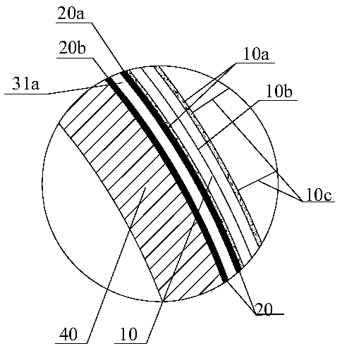
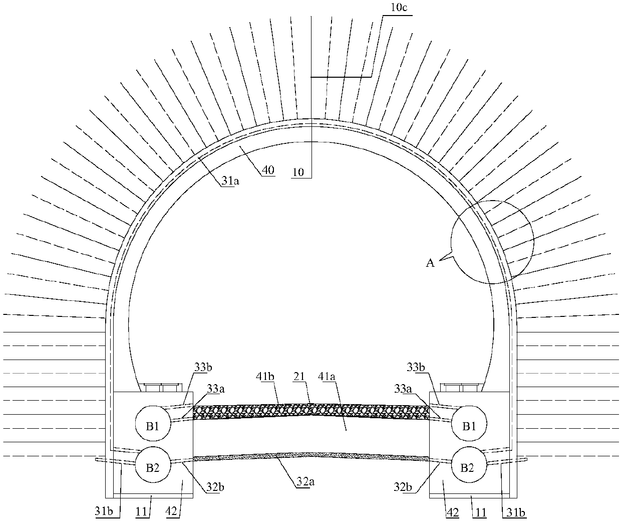
[0039] refer to figure 1 , the double-hole hollow rectangular section beam of the present invention bears the cutting-type arched tunnel lining structure and the separate drainage system, including the arch wall primary support structure 10, the arch wall secondary lining structure 40 and the arch wall range waterproof layer 20, and also includes drainage. system 30. The bottoms of the side walls on both sides of the secondary lining structure 40 of the arch wall are provided with longitudinal beams 42 that are consolidated with them, and the longitudinal beams 42 are rectangular cross-sections with an upper longitudinal cavity B1 and a lower longitudinal cavity B2. The longitudinal beams 42 not only serve as the bearing structure of the primary support structure 10 of the arch wall and the secondary lining structure 40 of the arch wall, but also serve...


PUM


Abstract

The invention discloses a dual-hole hollow rectangular section bearing cutting type arched tunnel lining structure and a separation drainage system. The effect of underground water on a tunnel liningbottom structure is eliminated, the problem that at a karst or underground development region, a tunnel inverted arch floats and deforms or a tunnel bottom structure is cracked and broken is effectively solved, the tunnel construction and operation stability and safety are ensured, and the phenomenon that ballast bed accumulated water inside a tunnel pollutes underground water during operation isavoided. Longitudinal beams fixedly connected to an arch wall secondary lining structure are arranged at the bottoms of the two side walls of the arch wall secondary lining structure, and each longitudinal beam is of a rectangular section with an upper longitudinal cavity and a lower longitudinal cavity. The longitudinal beams are adopted as bearing structures for an arch wall preliminary supporting structure and the arch wall secondary lining structure and also adopted as a tunnel longitudinal drainage channel. A replacement filling foundation composed of a foundation surface layer and a foundation bottom layer is arranged at the portion, between the longitudinal beams, of the bottom of the tunnel. An in-vivo excretory system introduces ballast bed accumulated water inside the tunnel intothe upper longitudinal cavities, and an in-vitro excretory system introduces water catchment of an arch wall range drainage system and a tunnel bottom drainage system into the lower longitudinal cavities.

Description

technical field [0001] The present invention relates to tunnel lining and drainage system structure, in particular to a tunnel lining structure and its waterproof and drainage system structure applied to groundwater development areas or areas where groundwater is affected by seasons irregularly or karst areas. Background technique [0002] Since the beginning of the 21st century, my country's railway construction has developed rapidly, and more and more high-standard double-track railways have been constructed with a speed of over 200km / h. Especially in the southwestern mountainous area, on the one hand, due to the widespread distribution of limestone strata; on the other hand, for high-speed railways, the line extension is restricted by various factors such as large curve radius and complex topographic and geological conditions, resulting in the scale (number and length) of karst tunnels. Rapid increase. Due to the complexity, diversity and irregularity of karst and karst ...

Claims


Application Information

Patent Timeline
Patent Type & Authority Applications(China)
IPC IPC(8): E21D11/00E21D11/04E21F16/02
CPCE21D11/00E21D11/04E21F16/02
Inventor 卿伟宸陶伟明郑伟林本涛张磊钟昌桂朱勇李泽龙张慧玲王芳孟祥磊
Owner CHINA RAILWAY ERYUAN ENG GRP CO LTD
Why Eureka
Try Eureka