Box-type base and bridge-type tunnel bottom structure dynamic-static separation bearing-type lining structure and drainage system thereof

A drainage system, dynamic and static separation technology, applied in tunnel lining, drainage, wellbore lining and other directions, can solve problems such as cracking and damage of underground tunnel bottom structure, achieve the effect of clear force, avoid mud and mud at the bottom of the tunnel, and save masonry

Pending Publication Date: 2018-09-28
CHINA RAILWAY ERYUAN ENG GRP CO LTD
View PDF7 Cites 1 Cited by
  • Summary
  • Abstract
  • Description
  • Claims
  • Application Information

AI Technical Summary

Problems solved by technology

[0020] The technical problem to be solved by the present invention is to provide a dynamic and static separation load-bearing lining structure and drainage system for the box-shaped foundation and the bridge-type tunnel bottom structure. The form and drainage system can eliminate the effect of groundwater on the bottom structure of the tunnel lining, effectively solve the problems of areas where groundwater develops, areas where groundwater is irregularly affected by seasons, and karst areas. stability and security

Method used


Image

  • Box-type base and bridge-type tunnel bottom structure dynamic-static separation bearing-type lining structure and drainage system thereof
  • Box-type base and bridge-type tunnel bottom structure dynamic-static separation bearing-type lining structure and drainage system thereof
  • Box-type base and bridge-type tunnel bottom structure dynamic-static separation bearing-type lining structure and drainage system thereof

Examples


Embodiment Construction

[0040] The present invention will be described in detail below in conjunction with the accompanying drawings and embodiments.

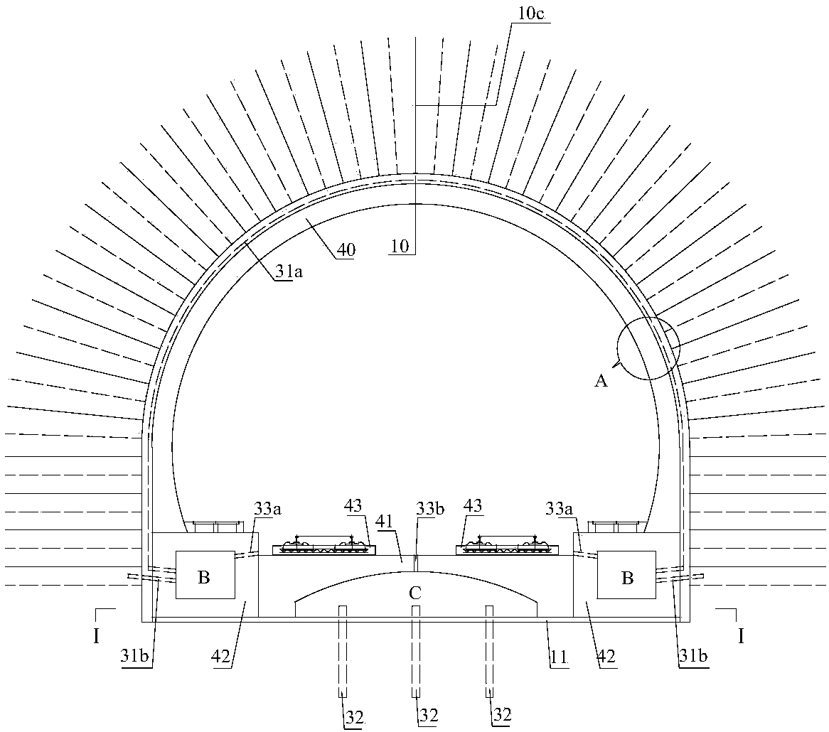
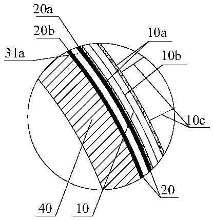
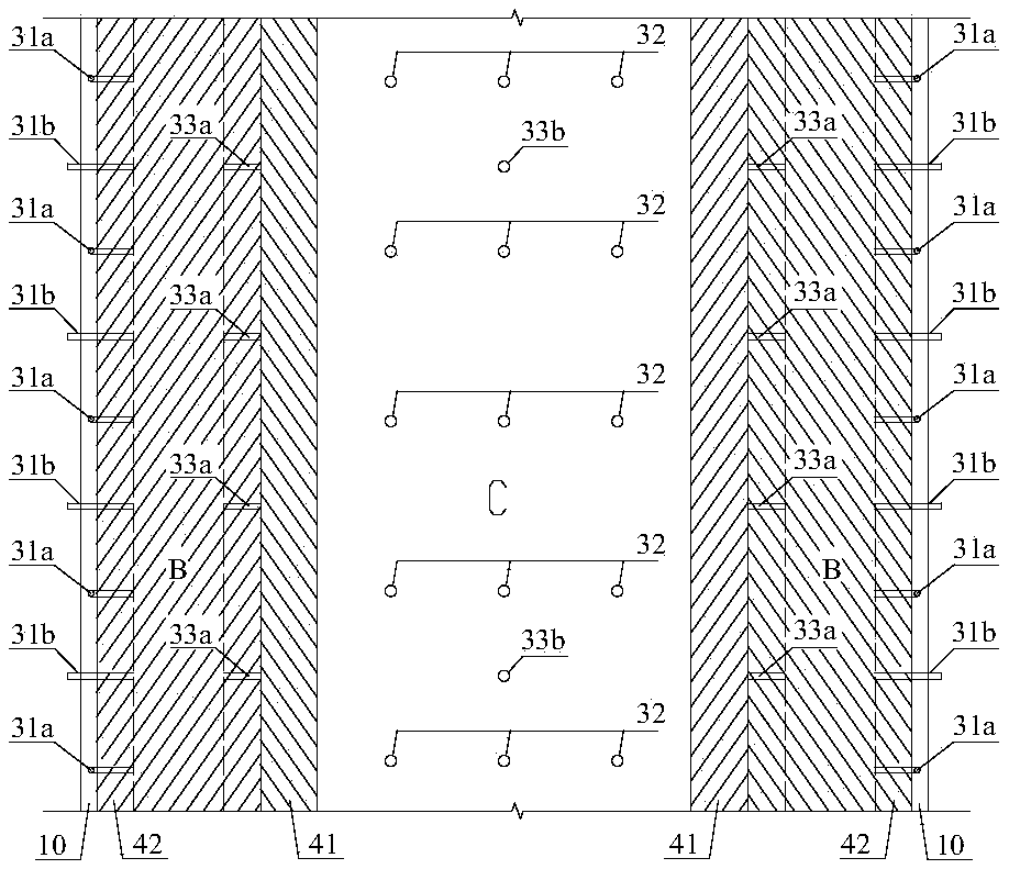
[0041] refer to figure 1 , Figure 4 and Figure 5 , the dynamic and static separation load-bearing lining structure of the box-shaped base and the bridge-type tunnel bottom structure of the present invention and its drainage system include the primary support structure 10 of the arch wall, the secondary lining structure 40 of the arch wall and the waterproof layer 20 in the range of the arch wall, and drainage system. The bottom of the two side walls of the arch wall secondary lining structure 40 is provided with a box-shaped base 42 integrated with it, as the load-bearing structure of the arch wall secondary lining structure 40, the box-shaped base 42 has a through longitudinal cavity B is used as the longitudinal drainage channel of the tunnel. A bridge-type tunnel bottom structure is arranged between the box-shaped foundations 42 on both sides...


PUM


Abstract

A box-type base and bridge-type tunnel bottom structure dynamic-static separation bearing-type lining structure and a drainage system thereof aim to eliminate the effect of underground water on a tunnel lining bottom structure, effectively solve the problem of tunnel inverted arch upwards-floating deformation or tunnel bottom structure cracking damage to an underground water development section, an underground water irregular section affected by the season and a karst area, and ensure the stability and safety of tunnel construction and operation. Box-type bases fixedly connected with an arc wall secondary lining structure into a whole are arranged at the bottoms of edge walls on the two sides of the arc wall secondary lining structure, and serving as a bearing structure of the arc wall secondary lining structure, the box-type bases are provided with through longitudinal cavities to serve as tunnel longitudinal drainage channels. A bridge-type tunnel bottom structure forming transversesupporting on the box-type bases is formed between the box-type bases on the two sides and serves as a bearing structure of a ballast bed and a train load. A through lower space is formed between thelower portion of the bridge-type tunnel bottom structure and the tunnel bottom excavation face and serves as a tunnel bottom underground water longitudinal drainage channel. An arc wall range drainagesystem communicates with the longitudinal cavities, a ballast bed accumulated-water drainage system communicates with the longitudinal cavities and the lower space, and the tunnel bottom drainage system communicates with the lower space.

Description

technical field [0001] The invention relates to tunnel lining and drainage system structure, in particular to a tunnel lining and its anti-drainage system structure used in areas with developed groundwater or areas with irregular groundwater affected by seasons or karst areas. Background technique [0002] Since the beginning of the 21st century, my country's railway construction has developed rapidly, and more and more high-standard double-track railways with a speed of more than 200km per hour have been built. Especially in the southwestern mountainous area, on the one hand, due to the widespread distribution of limestone formations; on the other hand, for high-speed railways, the line development is restricted by various factors such as large curve radius and complex terrain and geological conditions, resulting in the scale (number and length) of karst tunnels. Rapid increase. Due to the complexity, diversity, and irregularity of karst and karst water development, the ri...

Claims


Application Information

Patent Timeline
Patent Type & Authority Applications(China)
IPC IPC(8): E21D11/00E21D11/10E21D11/38E21F16/02
CPCE21D11/003E21D11/10E21D11/38E21F16/02
Inventor 卿伟宸朱勇陶伟明张磊林本涛李泽龙郑伟钟昌桂吴华王加一熊国兴
Owner CHINA RAILWAY ERYUAN ENG GRP CO LTD
Why Eureka
Try Eureka