A locking bar floating installation mechanism and installation method

A technology of installation mechanism and locking strip, which is applied in the direction of support structure installation, clamping/extracting device, etc., can solve the problem of easy locking of locking strip, and achieve the problems of wedge locking, convenient use and avoiding locking Effect

Active Publication Date: 2019-11-15
XIAN AVIATION COMPUTING TECH RES INST OF AVIATION IND CORP OF CHINA
View PDF5 Cites 0 Cited by
  • Summary
  • Abstract
  • Description
  • Claims
  • Application Information

AI Technical Summary

Problems solved by technology

[0003] Purpose of the present invention: to solve the problem that the locking bar is easy to lock

Method used


Image

  • A locking bar floating installation mechanism and installation method
  • A locking bar floating installation mechanism and installation method
  • A locking bar floating installation mechanism and installation method

Examples


Embodiment Construction

[0015] The present invention is further described below in conjunction with accompanying drawing:

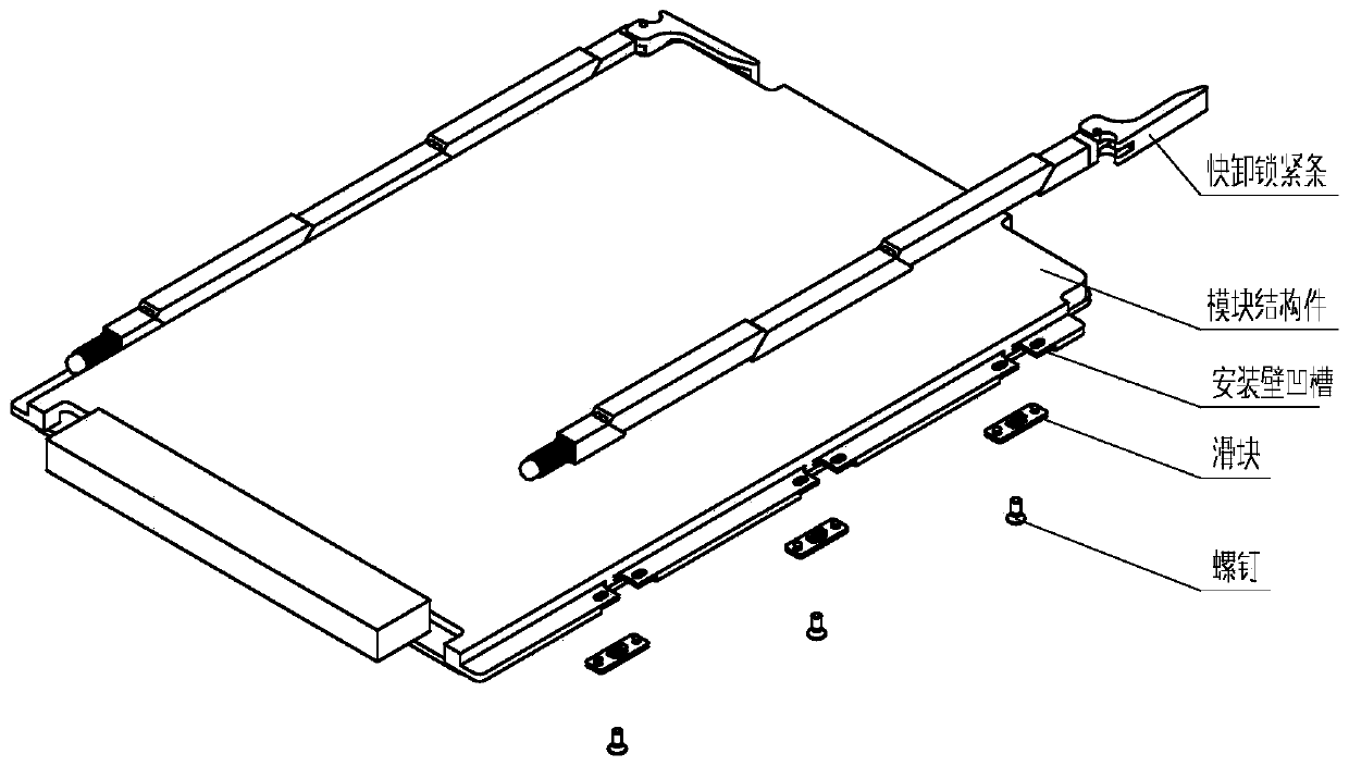
[0016] like figure 1 As shown, a locking bar floating installation mechanism includes a quick-release locking bar and screws, and the quick-release locking bar is fixed to the module structure through screws. It is characterized in that the quick-release locking bar is fixedly connected to the installation wall of the module structure A slider is added at the place to cooperate with the groove of the installation wall of the module structure to form a relatively sliding installation mechanism.

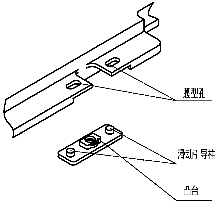
[0017] like figure 2 As shown, the slider is a sheet structure, with screw mounting holes and bosses in the middle, and sliding guide columns on both sides, which cooperate with the waist-shaped holes at both ends of the groove of the module structure installation wall. The height of the boss must be greater than the wall thickness of the joint of the module structure. The height of ...


PUM


Abstract

The invention belongs to the technical field of electronic equipment mechanical structures, and relates to a locking strip float mounting mechanism and a mounting method thereof. A float mounting mechanism is employed, grooves and slide blocks are arranged in mounting walls of a module structure, locking strips can be mounted on the module structure in a float manner, only a positive extrusion force is generated between each locking strip and a corresponding guide-track groove, the locking strip and the corresponding guide-track groove do not generate sliding friction, and locking of the locking strips is avoided. The locking strip float mounting mechanism is simple in structure and convenient to use, and can effectively overcome the locking problem of locking strip wedge blocks.

Description

technical field [0001] The invention belongs to the technical field of mechanical structures of electronic equipment, and relates to a locking bar floating installation mechanism and an installation method. Background technique [0002] At present, there is a locking strip that can be disassembled without tools, which is composed of a wedge, a slide bar, an elastic component, and a cam lifting mechanism. Through the rotation of the cam of the lifting mechanism, the wedge is driven to move on the slide bar, and the wedge is squeezed. The elastic component generates locking force to realize the module locking function. This kind of locking bar is installed through screws and connected to the threaded holes on the slide bar. If the slide bar is directly fixed to the module structure, the wedge block and the guide rail groove are likely to stick to each other due to the relative sliding friction between the wedge block and the guide rail groove during use. The situation causes ...

Claims


Application Information

Patent Timeline
Patent Type & Authority Patents(China)
IPC IPC(8): H05K7/14
CPCH05K7/1404
Inventor 醋强一焦超锋
Owner XIAN AVIATION COMPUTING TECH RES INST OF AVIATION IND CORP OF CHINA
Why Eureka
Try Eureka