Residue cleaning device used for sewage treatment

A cleaning device and sewage treatment technology, applied in water/sewage treatment, water/sewage multi-stage treatment, water/sludge/sewage treatment, etc., can solve the problems of poor treatment effect, large resources, complicated operation process, etc.

Active Publication Date: 2018-05-04
SHENZHEN JILONG CONTAMINATION CONTROL TECH
View PDF6 Cites 8 Cited by
  • Summary
  • Abstract
  • Description
  • Claims
  • Application Information

AI Technical Summary

Benefits of technology

This patented system allows for easy removal or maintenance of filters used in wastewater disposal systems without having any external tools like rods or hydraulics. It achieves these technical benefits such as simplifying operations, reducing resource usage, enabling effective filtration, ensuring complete washing results, and minimized environmental impact caused by the movement of components during lifting mechanisms.

Problems solved by technology

The technical problem addressed in this patented technology relates to developing a simpler and more effective method or apparatus for disposal of wastes from industrial processes such as manufacturing plants without causing environmental harm during their production.

Method used


Image

  • Residue cleaning device used for sewage treatment
  • Residue cleaning device used for sewage treatment
  • Residue cleaning device used for sewage treatment

Examples


Embodiment 1

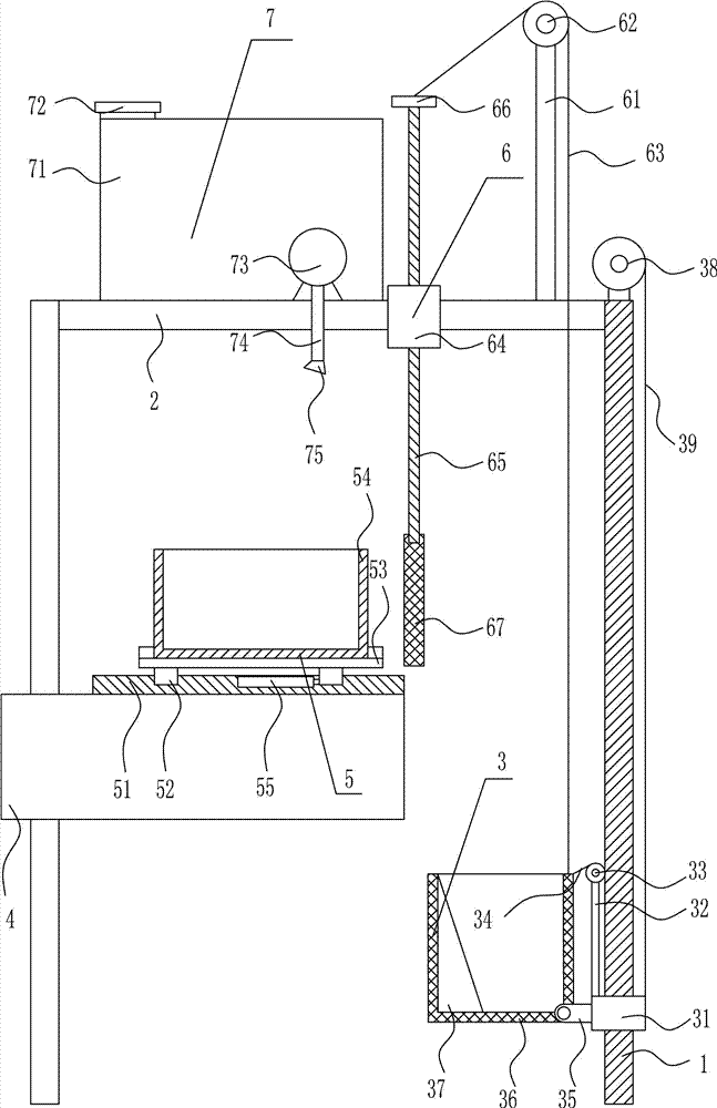
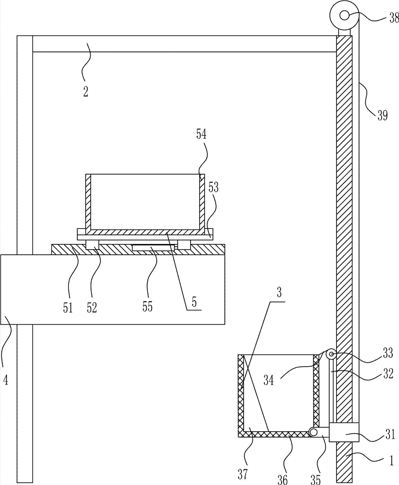
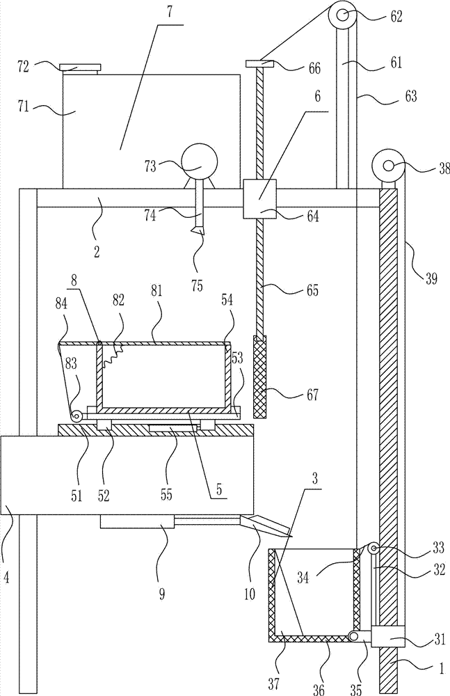
[0029] A kind of residue cleaning device for sewage treatment, such as Figure 1-3 As shown, it includes a support leg 1, a first support plate 2, a mobile filter mechanism 3, a material guide tube 4 and a collection mechanism 5. The top of the left and right support legs 1 is provided with a first support plate 2, and the right support leg 1 A mobile filter mechanism 3 is installed on the top, a material guide pipe 4 is provided in the middle part of the left side, and a collection mechanism 5 is installed on the top of the material guide pipe 4 .

Embodiment 2

[0031] A kind of residue cleaning device for sewage treatment, such as Figure 1-3 As shown, it includes a support leg 1, a first support plate 2, a mobile filter mechanism 3, a material guide tube 4 and a collection mechanism 5. The top of the left and right support legs 1 is provided with a first support plate 2, and the right support leg 1 A mobile filter mechanism 3 is installed on the top, a material guide pipe 4 is provided in the middle part of the left side, and a collection mechanism 5 is installed on the top of the material guide pipe 4 .

[0032] The mobile filter mechanism 3 includes a first slide block 31, a first support rod 32, a first electric reel 33, a first backguy 34, a second support plate 35, a net box 36, an inclined block 37, a second electric reel Wheel 38 and second stay wire 39, the supporting leg 1 on the right side is provided with the first slide block 31 that can slide up, the left side of the first slide block 31 top is vertically connected with...

Embodiment 3

[0034] A kind of residue cleaning device for sewage treatment, such as Figure 1-3 As shown, it includes a support leg 1, a first support plate 2, a mobile filter mechanism 3, a material guide tube 4 and a collection mechanism 5. The top of the left and right support legs 1 is provided with a first support plate 2, and the right support leg 1 A mobile filter mechanism 3 is installed on the top, a material guide pipe 4 is provided in the middle part of the left side, and a collection mechanism 5 is installed on the top of the material guide pipe 4 .

[0035] The mobile filter mechanism 3 includes a first slide block 31, a first support rod 32, a first electric reel 33, a first backguy 34, a second support plate 35, a net box 36, an inclined block 37, a second electric reel Wheel 38 and second stay wire 39, the supporting leg 1 on the right side is provided with the first slide block 31 that can slide up, the left side of the first slide block 31 top is vertically connected with...


PUM


Abstract

The invention relates to sewage treatment equipment, in particular relates to a residue cleaning device used for sewage treatment, and aims at providing a residue cleaning device which is used for thesewage treatment, simple in operation process and good in treatment effect and requires smaller resources. For achieving the aim, the provided residue cleaning device used for the sewage treatment comprises supporting legs and the like, wherein a first supporting plate is arranged at the top of the supporting legs at the left side and the right side, a movable filtration mechanism is arranged onthe supporting legs at the right side, a material guiding pipe is arranged at the middle part of the left side, and a collecting mechanism is arranged at the top of the material guiding pipe. The residue cleaning device used for the sewage treatment has the advantages that the movable filtration mechanism and the collecting mechanism cooperate with each other for treating sewage guided out from the material guiding pipe, and the optimization of an auxiliary mechanism and a disinfection mechanism is utilized, so that the effects of simple operation process, good treatment effect and smaller required resources are achieved.

Description


Claims


Application Information

Patent Timeline
Owner SHENZHEN JILONG CONTAMINATION CONTROL TECH
Why Eureka
Try Eureka