Wire saw

A wire saw and wire cutting technology, applied in the field of wire saw, can solve problems such as low-density frames, and achieve the effect of cost reduction

Active Publication Date: 2018-05-04
PRECISION SURFACING SOLUTIONS GMBH
View PDF14 Cites 0 Cited by
  • Summary
  • Abstract
  • Description
  • Claims
  • Application Information

AI Technical Summary

Problems solved by technology

The object of the present invention is to use a frame which has a lower weight and / or a lower density and / or allows easier manufacture of the frame, but at the same time ensures a high cutting quality by overcoming the problem of deformation of the frame

Method used


Image

  • Wire saw
  • Wire saw
  • Wire saw

Examples


Embodiment Construction

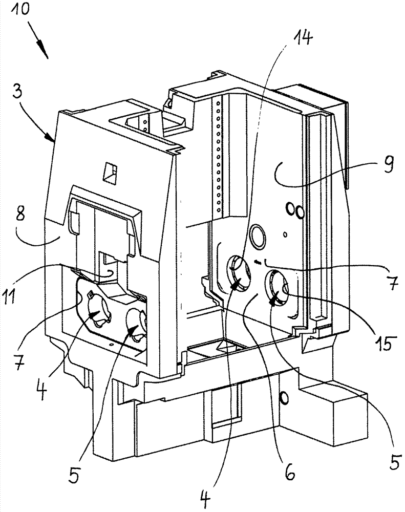
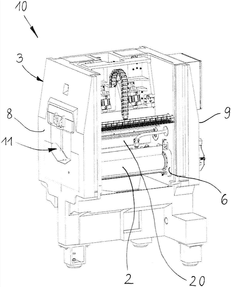
[0055] figure 2 and image 3 A wire saw 10 according to the invention is shown for cutting a block of material 20 , in particular for slicing, squaring and / or squaring a block of material such as hard and brittle material and / or semiconducting material. figure 1 Shows figure 2 Frame 3 of the jigsaw 10 shown in .

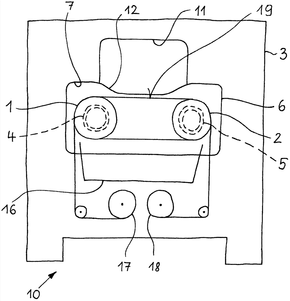
[0056] The wire saw 10 comprises a first wire guide roller 1 and a second wire guide roller 2 for supporting a cutting area 19 formed by the cutting wire. The frame 3 supports the wire guide rollers 1 and 2, and is made of a first material. Wire guide rollers 1 and 2 are rotatably mounted to frame 3 through bearings 4 and 5 .

[0057] The wire saw 10 comprises at least one common bearing housing 6 in which a first bearing 4 for supporting the first wire guiding roller 1 and a second bearing 5 for supporting the second wire guiding roller 2 are housed. exist figure 1 and figure 2 In the preferred embodiment of the present invention, the wire saw 10 comprises...


PUM

PropertyMeasurementUnit
thicknessaaaaaaaaaa
weightaaaaaaaaaa

Abstract

The invention relates to a wire saw (10) for cutting material blocks, the wire saw comprising a first wire guide roller (1) and a second wire guide roller (2) for supporting a cutting field (19) formed from cutting wires; and a frame (3) supporting the wire guide rollers (1, 2) and made of a first material, wherein the wire guide rollers (1, 2) are rotatably mounted to the frame (3) via bearings (4, 5). The invention is characterized in that the wire saw (10) comprises at least one common bearing block (6), in which a first bearing (4) supporting the first wire guide roller (1) and a second bearing (5) supporting the second wire guide roller (2) are accommodated, wherein the at least one common bearing block (6) is made of a second material and is mounted to the frame (3), and wherein Young's modulus of the second material is higher, preferably at least 3 times higher, than Young's modulus of the first material.

Description

technical field [0001] The invention relates to a wire saw according to the preamble of claim 1 and a method of manufacturing a wire saw according to the preamble of claim 25 . Background technique [0002] EP2826582B1 discloses a wire saw having a frame and four openings for receiving a set of wire guide rollers. The associated frame is made of mineral castings and incorporates four bearing housings, and one or more temperature controlled guard sections. The associated frame has two openings 102 for rotation axes 103 . The bearing sleeve 130 is disposed in the opening 102, generally by gluing and / or crimping. Forces acting on the wire guide rollers and forces between the wire guide rollers are transmitted to the inside of the frame through the bearing sleeves. The temperature control guard part only has a cooling / heating function. The disadvantage of this construction is that, in order to reliably absorb the forces arising from the tensioning of the wires in the wire me...

Claims


Application Information

Patent Timeline
Patent Type & Authority Applications(China)
IPC IPC(8): B23D57/00
CPCB23D57/0007B23D57/0061B23D57/0053
Inventor 马库斯·伯格亚历克斯·贝希勒尔
Owner PRECISION SURFACING SOLUTIONS GMBH
Why Eureka
Try Eureka