
Laser marking machine and application method thereof

A laser marking machine and laser technology, applied in the field of laser marking machines, can solve the problems of high dimensional accuracy requirements and low production efficiency, and achieve the effects of improving marking efficiency, improving production efficiency, and enhancing the degree of automation

Active Publication Date: 2018-05-04
HANS LASER TECH IND GRP CO LTD
View PDF7 Cites 12 Cited by
  • Summary
  • Abstract
  • Description
  • Claims
  • Application Information

AI Technical Summary

Problems solved by technology

[0003] Based on this, it is necessary to provide a laser marking machine and its use method in view of the problems of low production efficiency and high dimensional accuracy requirements when the existing laser marking machine marks different surfaces of the workpiece

Method used


Image

  • Laser marking machine and application method thereof
  • Laser marking machine and application method thereof
  • Laser marking machine and application method thereof

Examples


Embodiment Construction

[0034] In order to facilitate the understanding of the present invention, the present invention will be described more fully below with reference to the associated drawings. Preferred embodiments of the invention are shown in the accompanying drawings. However, the present invention can be embodied in many different forms and is not limited to the embodiments described herein. On the contrary, the purpose of providing these embodiments is to make the disclosure of the present invention more thorough and comprehensive.

[0035] It should be noted that when an element is referred to as being “fixed” to another element, it can be directly on the other element or there can also be an intervening element. When an element is referred to as being "connected to" another element, it can be directly connected to the other element or intervening elements may also be present. The terms "inner", "outer", "left", "right" and similar expressions are used herein for the purpose of descripti...


PUM


Abstract

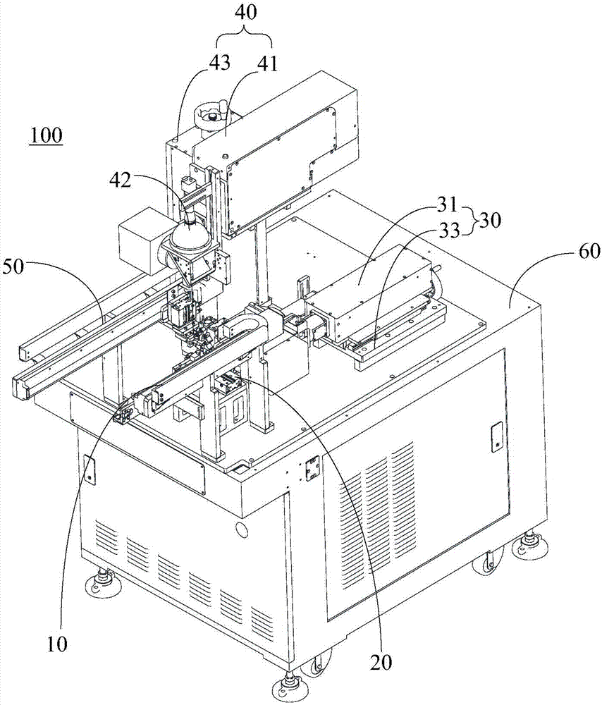
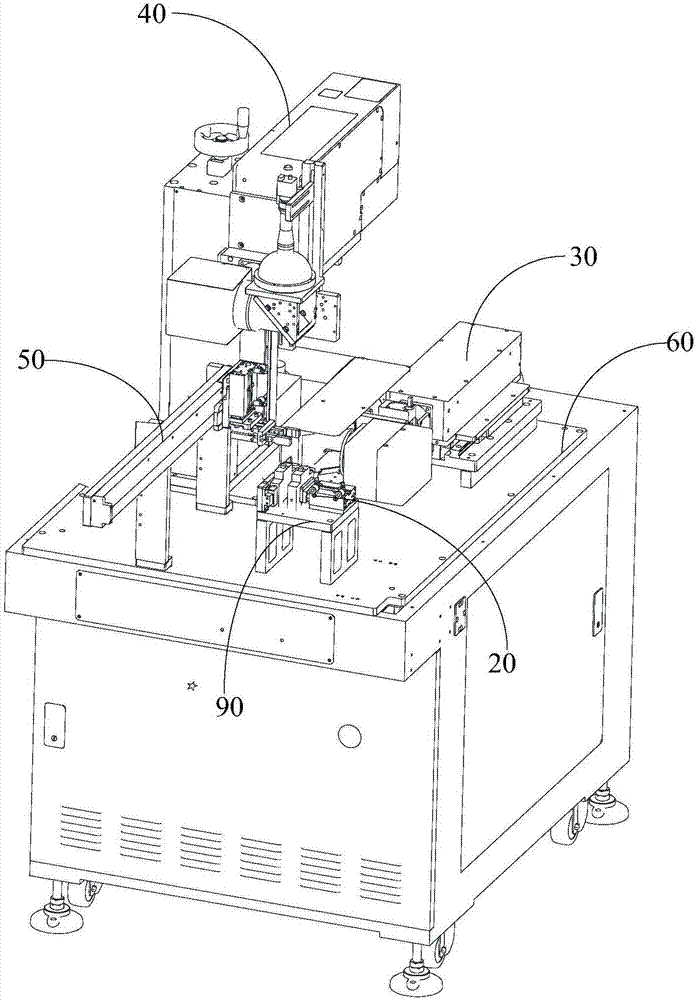
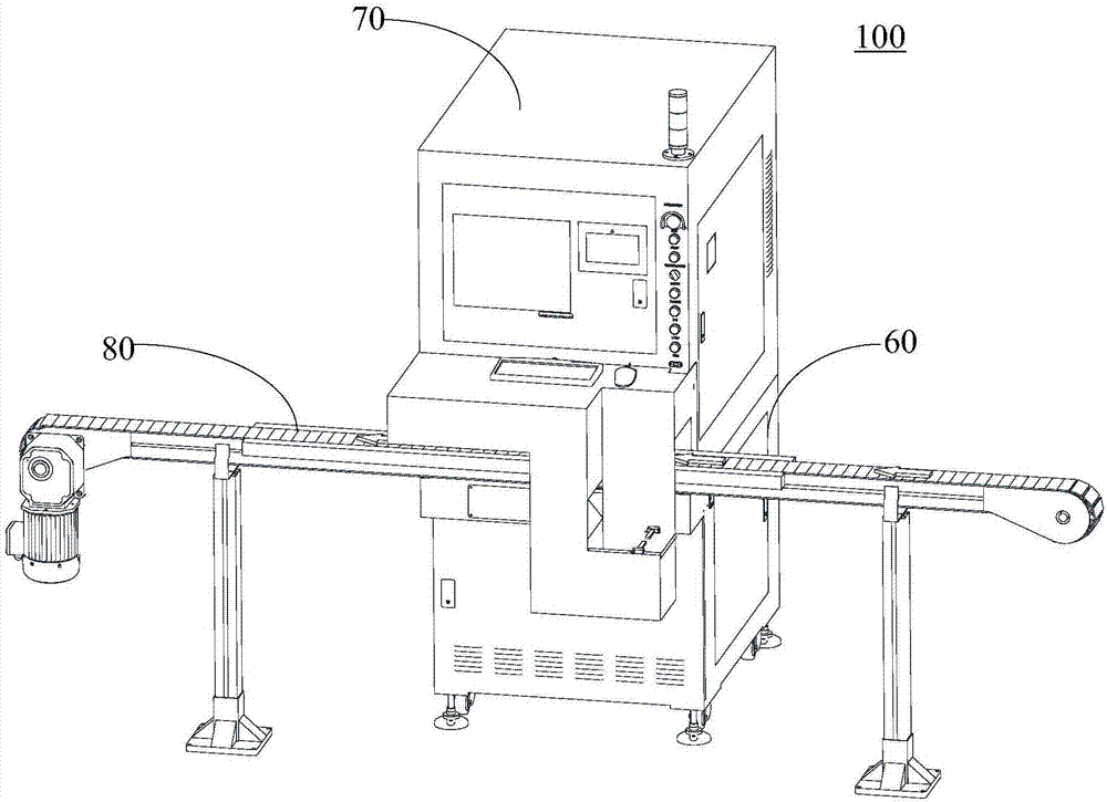
The invention relates to a laser marking machine. The laser marking machine comprises a loading mechanism for transferring workpieces to a loading table, a first marking mechanism comprises a first layer, a second marking mechanism erected above the loading table, and an unloading mechanism for shifting marked workpieces from the loading table, wherein the first laser is arranged towards the sidesurface of the loading table for marking the side surfaces of the workpieces on the loading table; and the second laser is arranged towards the top surface of the loading table for marking the top surfaces of the workpieces on the loading table. The laser marking machine is higher in working efficiency.

Description

technical field [0001] The invention relates to the technical field of laser equipment, in particular to a laser marking machine and its usage method. Background technique [0002] Existing laser marking machines usually only include one marking head. When it is necessary to mark different surfaces of the workpiece separately, it needs to be carried out sequentially, which takes a long time and leads to low production efficiency; in addition, when the size of the workpiece to be processed is small (such as air switch), the dimensional accuracy of the marking head transfer process is required to be high, which increases the difficulty of manufacturing the laser marking machine. Contents of the invention [0003] Based on this, it is necessary to provide a laser marking machine and a method of using the existing laser marking machine for the problems of low production efficiency and high dimensional accuracy when marking different surfaces of workpieces. [0004] A laser ma...

Claims


Application Information

Patent Timeline
IPC IPC(8): B23K26/362B23K26/70
CPCB23K26/361B23K26/702
Inventor 郭缙刘康王波邓云强张向阳廖文胡杰胡述旭杨柯刘亮曹洪涛吕启涛高云峰
Owner HANS LASER TECH IND GRP CO LTD
Learn More