Laser marking equipment

A technology of laser marking and equipment, applied in the field of marking, can solve the problems of low degree of automation and low efficiency

Pending Publication Date: 2018-06-15
GUANGDONG ZHENGYE TECH
View PDF0 Cites 5 Cited by
  • Summary
  • Abstract
  • Description
  • Claims
  • Application Information

AI Technical Summary

Problems solved by technology

[0005] In view of this, the object of the present invention is to provide a laser marking equipment, the structural design of t

Method used


Image

  • Laser marking equipment
  • Laser marking equipment
  • Laser marking equipment

Examples


Embodiment Construction

[0026] The embodiment of the invention discloses a laser marking device to improve the automation degree and efficiency of the device.

[0027] The following will clearly and completely describe the technical solutions in the embodiments of the present invention with reference to the accompanying drawings in the embodiments of the present invention. Obviously, the described embodiments are only some, not all, embodiments of the present invention. Based on the embodiments of the present invention, all other embodiments obtained by persons of ordinary skill in the art without making creative efforts belong to the protection scope of the present invention.

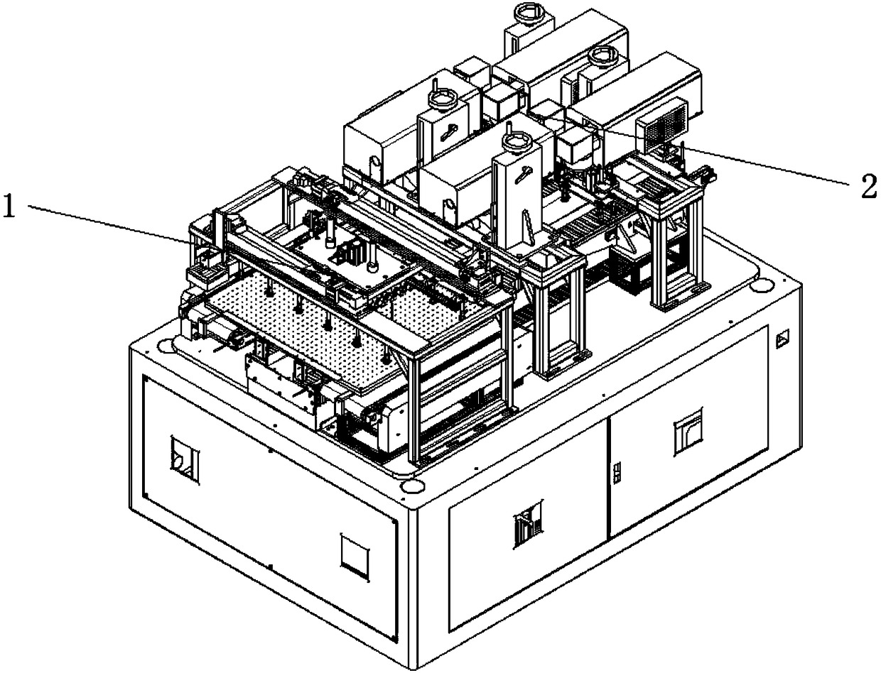
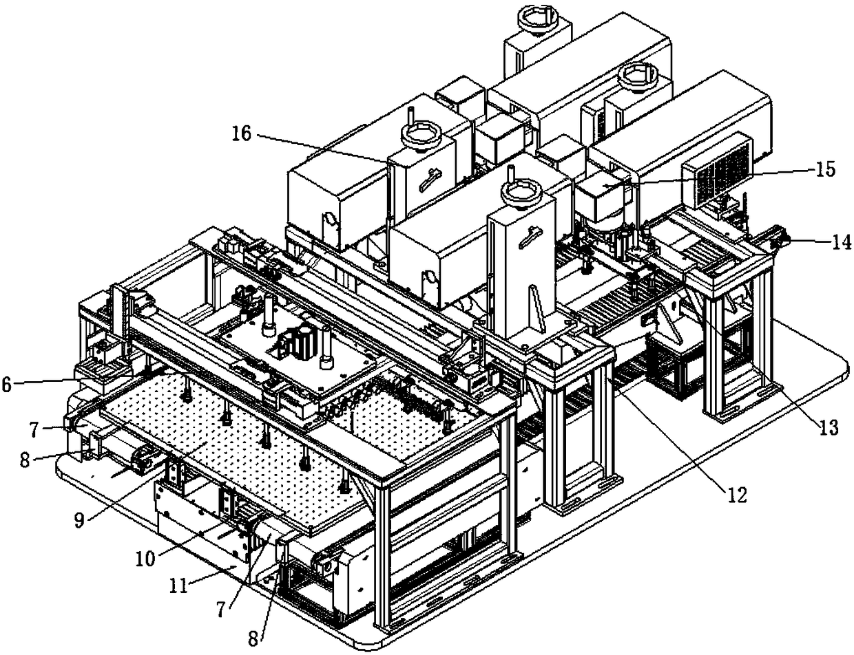
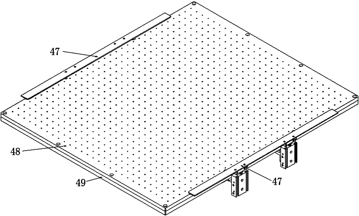
[0028] see Figure 1-Figure 4 , figure 1 It is a schematic structural diagram of a laser marking device according to a specific embodiment of the present invention; figure 2 for figure 1 Schematic diagram of the local structure of the camera station and marking station; image 3 is a schematic diagram of the local struct...


PUM


Abstract

The invention discloses laser marking equipment. The equipment comprises a base, wherein a camera station and a marking station are arranged on the base, a feeding assembly used for driving a printedcircuit board to move is arranged on one side of the camera station, and a discharging assembly used for driving the printed circuit board to move is arranged on one side of the marking station; and the equipment further comprises an adsorption platform assembly used for adsorbing and fixing the printed circuit board, a feeding lifting suction plate assembly and a discharging lifting suction plateassembly, wherein the adsorption platform assembly can move to the camera station and the marking station under driving of a platform driving assembly, the discharging lifting suction plate assemblyis used for transferring the printed circuit board on the adsorption platform assembly to the discharging assembly, and the feeding lifting suction plate assembly is used for transferring the printedcircuit board on the feeding assembly to the adsorption platform assembly. According to the laser marking equipment, the camera station and the marking station are mutually independent and can work atthe same time; and the adsorption platform assembly can quickly and efficiently position boards, and positioning accuracy is guaranteed.

Description

technical field [0001] The present invention relates to the technical field of marking, and more specifically, to a laser marking device. Background technique [0002] With the continuous advancement of science and technology, the continuous improvement of people's living standards, the continuous development of smart phone technology and wearable electronic technology, intelligence, thinness, and miniaturization have become the mainstream, and consumers have higher and higher quality requirements for products. Therefore, the quality control of internal PCB circuit boards is becoming more and more strict. It is necessary to strive for excellence in order to win consumers, win the recognition of customers, and realize secondary purchases. [0003] In order to realize the quality control of PCB, the means usually used is laser marking technology. That is, mark strings, one-dimensional codes, two-dimensional codes and other information on the PCB board, upload them to the data...

Claims


Application Information

Patent Timeline
IPC IPC(8): B23K26/362B23K26/70
CPCB23K26/361B23K26/702
Inventor 侯志松赵建涛白天喜李金江林克梅领亮徐地明张善基温琪黄应财王征龚成万
Owner GUANGDONG ZHENGYE TECH
Why Eureka
Try Eureka