Special single-moment-arm and double-working-station clamp for machining

A kind of mechanical processing and double-station technology, applied in the direction of manufacturing tools, metal processing equipment, metal processing machinery parts, etc., can solve the problems of inconvenient processing and inflexible use, and achieve simple structure, flexible and convenient use, scientific and reasonable design Effect

Inactive Publication Date: 2018-05-04
芜湖挺优机电技术有限公司
0 Cites 0 Cited by

AI-Extracted Technical Summary

Problems solved by technology

[0003] The existing machining fixtures are mainly single-station fixtures, and the workpiece can only be clamped and fixed at one st...

Method used

[0011] In order to make the purpose of the present invention, technical solutions and advantages more clear, the following describes the present invention by specific embodiments shown in the accompanying drawings. It should be understood, however, that these desc...

Abstract

The invention discloses a special single-moment-arm and double-working-station clamp for machining. A left vertical plate is welded at the left side of a support plate through a triangular ribbed plate, a right vertical plate is welded at the right side of the support plate through a triangular ribbed plate, and a lever moment arm is mounted in the center of the support plate through an upper moving hinge pin. A left trapezoidal threaded hole is processed in the lower part of the left vertical plate, and a right trapezoidal threaded hole is processed in the lower part of the right vertical plate. A left screw is mounted in the left trapezoidal threaded hole, and a right screw is mounted in the right trapezoidal threaded hole. A movable clamping plate is mounted at the top end of the levermoment arm through a bolt, and a fixed clamping plate is welded on the right side wall of the left vertical plate and the left side wall of the right vertical plate. The design is scientific and reasonable, and the use is convenient.

Application Domain

Positioning apparatusMetal-working holders +1

Technology Topic

EngineeringMachining

Image

  • Special single-moment-arm and double-working-station clamp for machining

Examples

  • Experimental program(1)

Example Embodiment

[0011] In order to make the object, technical solution and advantages of the present invention clearer, the present invention is described below through specific embodiments shown in the accompanying drawings. It should be understood, however, that these descriptions are exemplary only and are not intended to limit the scope of the present invention. Also, in the following description, descriptions of well-known structures and techniques are omitted to avoid unnecessarily obscuring the concept of the present invention.
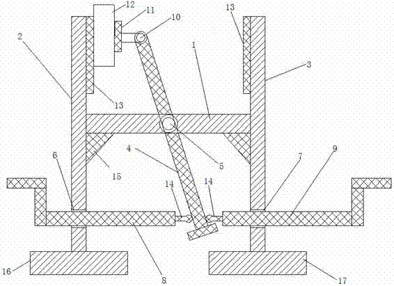
[0012] like figure 1 As shown, a single-arm double-station fixture dedicated to mechanical processing includes: a support plate 1, a left vertical plate 2, a right vertical plate 3, a lever force arm 4, an upper movable pin shaft 5, and a left trapezoidal threaded hole 6 , right trapezoidal threaded hole 7, left screw rod 8, right screw rod 9, bolt 10, movable clamping plate 11, workpiece 12, fixed clamping plate 13, ball head 14, triangular rib plate 15, left base 16, right base 17, The left vertical plate 2 is welded on the left side of the support plate 1 through the triangular rib plate 15, the right vertical plate 3 is welded on the right side of the support plate 1 through the triangular rib plate 15, and the lever arm 4 is passed through the upper movable pin The shaft 5 is installed in the center of the support plate 1, the left trapezoidal threaded hole 6 is processed at the bottom of the left vertical plate 2, the right trapezoidal threaded hole 7 is processed at the bottom of the right vertical plate 3, and the left screw rod 8 is installed in the left trapezoidal threaded hole 6 Inside, the right screw rod 9 is installed in the right trapezoidal threaded hole 7, the movable clamping plate 11 is installed on the top of the lever arm 4 through the bolt 10, and the fixed clamping plate 13 is welded on the right side of the left vertical plate 2 On the wall and on the left side wall of right riser 3.
[0013] Specifically, the ball head 14 is welded to the right end of the left screw 8 and the left end of the right screw 9, the left base 16 is welded to the bottom of the left vertical plate 2, and the right base 17 is welded to the bottom of the right vertical plate 3 , the workpiece 12 is clamped between the fixed clamping plate 13 and the movable clamping plate 11 .
[0014] In the technical solution of the present invention, the lever force arm is installed in the center of the support plate through the upper movable pin shaft, the left screw rod is installed in the left trapezoidal threaded hole, the right screw rod is installed in the right trapezoidal threaded hole, and the movable clamping plate passes through the bolt The design of the top installed on the lever force arm uses the left screw rod and the right screw rod to apply force to the lever force arm to realize the clamping and fixing of the workpiece by the movable clamping plate and the fixed clamping plate.
[0015] The basic principles and main features of the present invention and the advantages of the present invention have been shown and described above. Those skilled in the industry should understand that the present invention is not limited by the above-mentioned embodiments. What are described in the above-mentioned embodiments and the description only illustrate the principle of the present invention. Without departing from the spirit and scope of the present invention, the present invention will also have Variations and improvements are possible, which fall within the scope of the claimed invention. The protection scope of the present invention is defined by the appended claims and their equivalents.

PUM

no PUM

Description & Claims & Application Information

We can also present the details of the Description, Claims and Application information to help users get a comprehensive understanding of the technical details of the patent, such as background art, summary of invention, brief description of drawings, description of embodiments, and other original content. On the other hand, users can also determine the specific scope of protection of the technology through the list of claims; as well as understand the changes in the life cycle of the technology with the presentation of the patent timeline. Login to view more.

Similar technology patents

Intelligent conference system

Owner:HEILONGJIANG KANGGEER TECH

Classification and recommendation of technical efficacy words

  • Simple structure
  • Scientific and reasonable design

Sharing system for air-conditioning coat

InactiveCN107440179ASimple structureeasy to wear
Owner:QINGDAO HAIER AIR CONDITIONER GENERAL CORP LTD

Feeding device of sorter of batteries plate

InactiveCN101357717ASimple structurecooperate well
Owner:NANJING NORMAL UNIVERSITY

Emergency parachuting device and method for multiple-rotor unmanned aerial vehicle

InactiveCN103895870Aavoid aircraft crashSimple structure
Owner:SOUTH CHINA AGRI UNIV +1

Planting method for wild grape

Owner:广西都安密洛陀野生葡萄酒有限公司
Why Eureka
Try Eureka