Al technical title is built by PatSnap Al team. It summarizes the technical point description of the patent document.
A deceleration roadblock and functional technology, applied in the field of deceleration roadblocks, can solve problems such as vibration and deformation of roadblocks, energy loss, and accelerated aging of roadblocks.
Inactive Publication Date: 2018-05-04
朱小英
View PDF7 Cites 2 Cited by
Summary
Abstract
Description
Claims
Application Information
AI Technical Summary
This helps you quickly interpret patents by identifying the three key elements:
Problems solved by technology
Method used
Benefits of technology
Problems solved by technology
[0002] With the enhancement of people's energy awareness, the application of solar power generation, hydropower generation, wind power generation and other technologies is becoming more and more common. Roadblocks are set up in places with relatively large flow of people or vehicles or in areas with high accidents to limit driving speed. A kind of obstacle, most of the existing roadblocks are rubber roadblocks, when the vehicle passes through the roadblock, the gravity of the vehicle will cause the roadblock to vibrate and deform, and these energy often act directly on the roadblock, which accelerates the aging of the roadblock and causes energy loss and waste. If these energies are converted and used for street lights, warning lights and other electrical equipment on both sides of the road, it will not only save electricity, but also reduce the cost of infrastructure construction required for long-distance power transmission, but it has not yet been able to convert efficiently. This part of the energy device
Method used
Image
Click on the blue label to locate the original text in one second.
Reading with bidirectional positioning of images and text.
Examples
Embodiment Construction
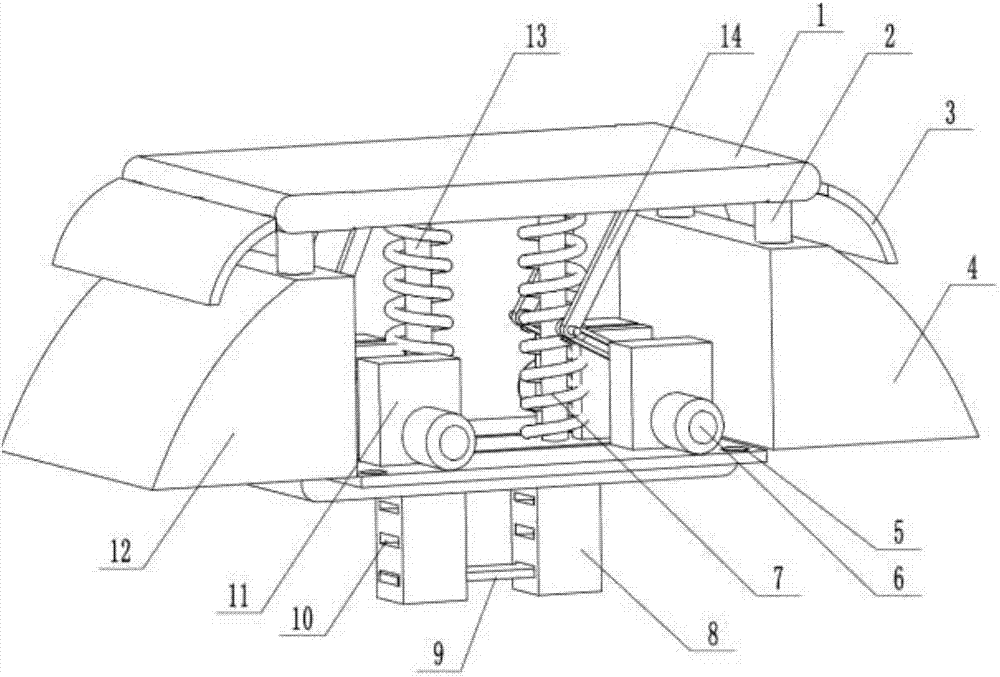
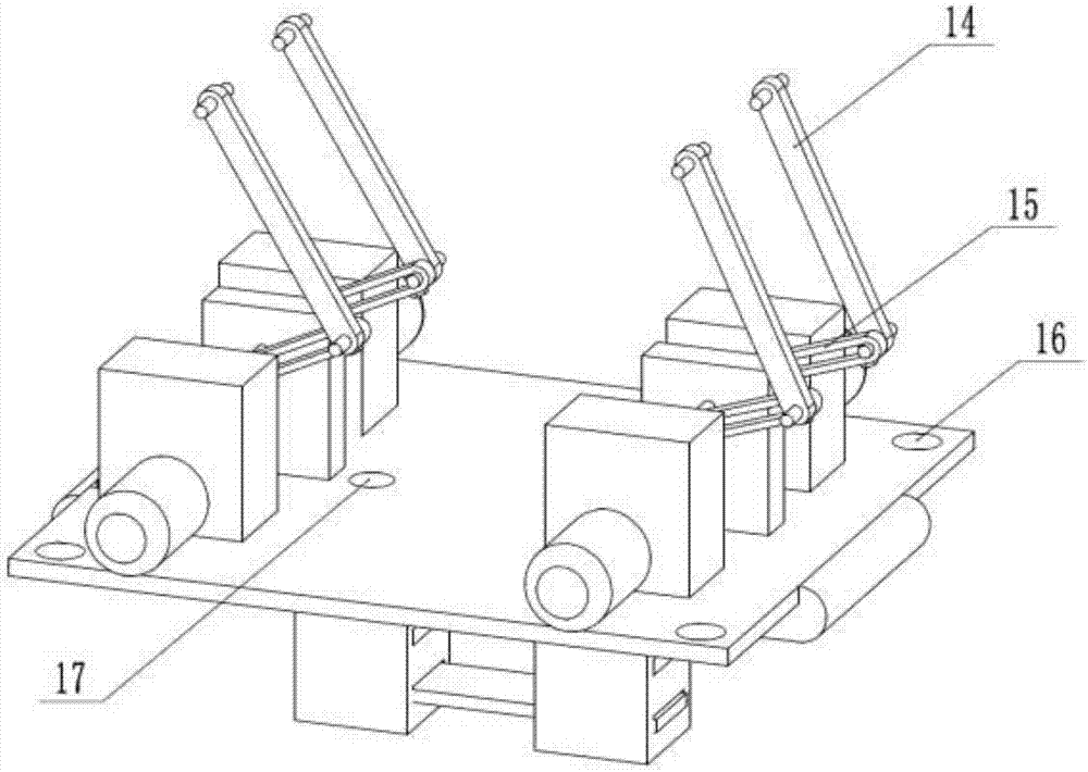
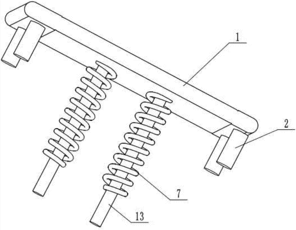
[0018] A deceleration roadblock with power generation function is composed of an upper platen 1, a guide column 2, a joint plate 3, a right base 4, a positioning base plate 5, a generator 6, a compression spring 7, a height adjustment cylinder 8, a limit plate 9, Positioning port 10, gear speed-up box 11, left base body 12, guide column two 13, connecting rod one 14, connecting rod two 15, positioning hole 16, guide hole two 17, base 18 and transmission main shaft 19 are formed, described The upper platen 1 is arranged above the left base body 12 and the right base body 4, and both ends of the upper platen 1 are provided with a guide post-2, and the guide post-2, the left base body 12 and the right base body 4 cooperate with the upper press plate 1 Guide, the connecting plate 3 is arranged between the left base body 12 and the upper pressing plate 1, the connecting plate 3 is arranged between the right base body 4 and the upper pressing plate 1, and the middle position of the u...
PUM
Abstract
The invention belongs to the field of road infrastructures and discloses a speed bump with a power generating function. The speed bump comprises an upper pressure plate, first guide columns, linkage plates, a right base, a positioning base plate, power generators, compression springs, height adjusting barrels, a limiting plate, positioning ports, gearboxes, a left base, second guide columns, firstconnecting rods, second connecting rods, positioning holes, a second guide hole, bases and transmission spindles. The upper pressure plate is arranged above the bases, the first guide columns are arranged at two ends of the upper pressure plate respectively, and the upper pressure plate is guided by cooperation of the first guide columns and the bases. The linkage plates are arranged between theleft base and the upper pressure plate, and correct guide of the upper pressure plate is realized by cooperation of the second guide columns and the compression springs. By height adjustment of the limiting plate, the speed bump can be adjusted to meet demands of people. By cooperation of the first connecting rods, the second connecting rods and the bases, stable and effective power input is realized. In addition, the speed bump is structurally compact, and effectiveness in power generation is achieved.
Description
technical field [0001] The invention relates to a deceleration roadblock with power generation function, in particular to a device which adopts a special mechanical structure to convert the energy generated by vehicles passing the roadblock into electric energy, and belongs to the field of road infrastructure. Background technique [0002] With the enhancement of people's energy awareness, the application of solar power generation, hydropower generation, wind power generation and other technologies is becoming more and more common. Roadblocks are set up in places with relatively large flow of people or vehicles or in areas with high accidents to limit driving speed. A kind of obstacle, most of the existing roadblocks are rubber roadblocks, when the vehicle passes through the roadblock, the gravity of the vehicle will cause the roadblock to vibrate and deform, and these energy often act directly on the roadblock, which accelerates the aging of the roadblock and causes energy l...
Claims
Application Information
Patent Timeline
Application Date:The date an application was filed.
Publication Date:The date a patent or application was officially published.
First Publication Date:The earliest publication date of a patent with the same application number.
Issue Date:Publication date of the patent grant document.
PCT Entry Date:The Entry date of PCT National Phase.
Estimated Expiry Date:The statutory expiry date of a patent right according to the Patent Law, and it is the longest term of protection that the patent right can achieve without the termination of the patent right due to other reasons(Term extension factor has been taken into account ).
Invalid Date:Actual expiry date is based on effective date or publication date of legal transaction data of invalid patent.