Ground ramming device

A ground and rammed plate technology, applied in soil protection, construction, infrastructure engineering, etc., can solve the problems of inability to apply hammering, thin rammed soil layer, insufficient impact force, etc., so as to avoid maintenance cost reduction and acceleration. Ramming efficiency, novel structure effect

Inactive Publication Date: 2018-05-04
HEFEI XIAKANG ELECTRONICS COMMERCE CO LTD
View PDF0 Cites 3 Cited by
  • Summary
  • Abstract
  • Description
  • Claims
  • Application Information

AI Technical Summary

Problems solved by technology

[0002] The existing tamping device relies on hydraulic vibration for tamping. This equipment has an inherent defect, the impact force is not enough, that is, the thickness of the hardened surface soil is relatively thin, and it cannot be used for hammering operations.
Specifically, the existing tamping device has the following defects: hydraulic vibration tamping, the thickness of the compacted soil layer is relatively thin; it cannot be applied to hammering operations; it cannot be applied to building demolition; the structure is complex, maintenance is inconvenient and the cost is high

Method used


Image

  • Ground ramming device

Examples


Embodiment Construction

[0014] The following will clearly and completely describe the technical solutions in the embodiments of the present invention with reference to the accompanying drawings in the embodiments of the present invention. Obviously, the described embodiments are only some, not all, embodiments of the present invention.

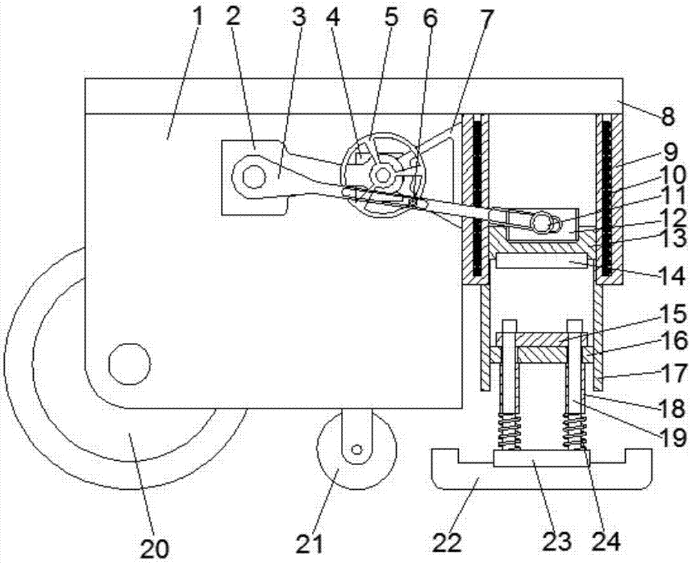
[0015] refer to figure 1 , a ground ramming device, comprising a cabinet 1, one end of the cabinet 1 is fixedly connected with a tank 9, the upper end of the cabinet 1 and the tank 9 is fixedly connected with a cover plate 8, the inside of the cabinet 1 is welded with a support frame 2, and the cabinet 1 A tripod 7 is welded on the inner wall near the tank body 9, and the tripod 7 and the support frame 2 are fixedly connected to form the support structure of the device. One end of the support frame 2 is rotatably connected to the swing rod 3, the support frame 2 and the tripod The connection of 7 is rotatably connected with a flywheel 5, and one end of the cabinet 1 ...


PUM


Abstract

The invention discloses a ground ramming device. The ground ramming device comprises a machine box, a tank body is fixedly connected to one end of the machine box, a cover plate is fixedly connected to the upper ends of the machine box and the tank body, and a supporting frame is welded inside the machine box; a tripod is welded to the inner side wall, close to the tank body, of the machine box, and the tripod and the supporting frame are fixedly connected; and a motor is fixedly connected to the end, close to the supporting frame, of the machine box, a swing rod is rotationally connected to one end of the supporting frame and is fixedly connected with an output shaft of the motor, a flywheel is rotationally connected to the connecting position between the supporting frame and the tripod,a first limiting wheel is rotationally connected to the flywheel, and a first hollow groove and a second hollow groove are formed in the swing rod. According to the device, the structure is novel, theoperation is stable, a hammer body can move up and down in a reciprocating mode to ram the ground through the transmission of the flywheel and the swing rod, the ground ramming device is higher in efficiency, the use of hydraulic transmission is avoided, so that the maintenance cost is reduced, the practicability is high, and the popularization is facilitated.

Description

technical field [0001] The invention relates to the technical field of ramming construction, in particular to a ground ramming device. Background technique [0002] The existing tamping device relies on hydraulic vibration to tamp. This equipment has an inherent defect, the impact force is not enough, that is, the thickness of the hardened surface soil is relatively thin, and it cannot be used for hammering operations. Specifically, the existing tamping device has the following defects: hydraulic vibration tamping, the thickness of the compacted soil layer is relatively thin; it cannot be applied to hammering operations; it cannot be applied to building demolition; it has a complicated structure, inconvenient maintenance and high cost. Contents of the invention [0003] The object of the present invention is to propose a ground ramming device in order to solve the shortcomings in the prior art. [0004] In order to achieve the above object, the present invention adopts th...

Claims


Application Information

Patent Timeline
Patent Type & Authority Applications(China)
IPC IPC(8): E02D3/074
CPCE02D3/074
Inventor 郭来财
Owner HEFEI XIAKANG ELECTRONICS COMMERCE CO LTD
Why Eureka
Try Eureka