Retaining wall system capable of reducing construction influence and construction method for retaining wall system

A retaining wall and anti-filter geotextile technology, which is applied in the field of engineering construction, can solve the problems of reducing the quality of the "V"-shaped backfill area, longitudinal cracks in the subgrade, and the quality of the drainage and anti-filter layer of the compact retaining wall cannot be guaranteed.

Active Publication Date: 2021-01-19
ANHUI TRANSPORT CONSULTING & DESIGN INST
View PDF6 Cites 2 Cited by
  • Summary
  • Abstract
  • Description
  • Claims
  • Application Information

AI Technical Summary

Problems solved by technology

Due to the narrow construction space, the quality of compaction, excavation steps, and retaining wall drainage and filter layer cannot be guaranteed. In the context of rising material prices, general fillers are often used to backfill the "V" groove during construction. The

Method used


Image

  • Retaining wall system capable of reducing construction influence and construction method for retaining wall system
  • Retaining wall system capable of reducing construction influence and construction method for retaining wall system
  • Retaining wall system capable of reducing construction influence and construction method for retaining wall system

Examples


Embodiment 1

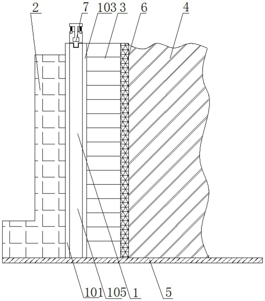
[0037] see Figure 1-4 , a retaining wall system for reducing the impact of construction, comprising an air pressure energy dissipation layer 1, an air pressure partition 105 and a ground line 5, a retaining wall 2 is arranged above the left side of the ground line 5, and an air pressure is arranged on the right side of the retaining wall 2 Energy dissipation layer 1, sandbag layer 3 is arranged on the right side of air pressure energy dissipation layer 1, and sandbag layer 3 is formed by stacking several sandbags, and filter geotextile 6 is arranged on the right side of sandbag layer 3. The right side of the cloth 6 is provided with an embankment fill 4 .

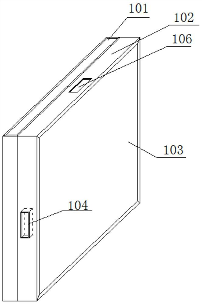
[0038] The air pressure energy dissipation layer 1 includes a packing channel 101, a metal frame 102, a rubber surface 103, a connecting slot 104, an air pressure partition 105 and a communication slot 106; the outer wall of the air pressure partition 105 is respectively wrapped with a metal frame 102 and a rubber surface ...

Embodiment 2

[0042] see Figure 1-4 , the construction method of the retaining wall system to reduce the construction impact is as follows:

[0043] S1. According to the design drawings of the retaining wall 2, stake out on site, excavate the foundation and check the bearing capacity of the groove base;

[0044] S2. Set up the formwork and pour concrete for the retaining wall, and maintain the concrete for the retaining wall until the strength reaches the requirement;

[0045] S3, install the air pressure energy dissipation layer 1, and connect the air pressure partition 105 according to the length of the filling and paving;

[0046] S4. Use an air pressure pump to inject air into the air pressure partition 105, use the air pressure monitoring device to monitor the internal air pressure, and maintain the internal pressure of the air pressure partition 105;

[0047] S5. The sandbag layer 3 is placed on the right side of the air pressure energy dissipation layer 1, and the filter geotextil...


PUM


Abstract

The invention discloses a retaining wall system capable of reducing the construction influence and a construction method for the retaining wall system, and relates to the field of engineering construction. The retaining wall system comprises an air pressure energy dissipation layer, an air pressure partition plate and a ground line, a retaining wall is arranged above the left side of the ground line, the air pressure energy dissipation layer is arranged on the right side of the retaining wall, and a sand bag layer is arranged on the right side of the air pressure energy dissipation layer; andan inverted filter geotextile is arranged on the right side of the sand bag layer, and embankment filling soil is arranged on the right side of the inverted filter geotextile. According to the retaining wall system capable of reducing the construction influence, through cooperation of the air pressure energy dissipation layer and an energy dissipation device, ramming force generated during embankment filling construction is effectively absorbed, and the situation that the retaining wall is damaged due to vibration generated by the ramming force during construction is avoided.

Description

Technical field: [0001] The invention relates to the field of engineering construction, in particular to a retaining wall system and a construction method for reducing construction impact. Background technique: [0002] The retaining wall is a structure to prevent the deformation and instability of filling or soil. In terms of limited land use and improving the stability of embankments, retaining walls are widely used in industries such as highways, municipalities, and waterways. On the premise that the construction does not affect the safety of the retaining wall structure, in order to ensure the compactness of the backfill of the abutment, the "Technical Specifications for Construction of Highway Subgrade" requires that the filler be made of water-permeable materials, lightweight materials, and inorganic binder stabilized materials. Use small-scale tamping equipment for compaction within 1.0m of the back of the wall, and the layered compaction thickness should not be great...

Claims


Application Information

Patent Timeline
IPC IPC(8): E02D29/02E01C3/04E02D3/046
CPCE01C3/04E02D3/046E02D29/0275
Inventor 张志峰石川李翻翻
Owner ANHUI TRANSPORT CONSULTING & DESIGN INST
Why Eureka
Try Eureka