Dust catcher equipment

A dust collector and equipment technology, applied in the direction of electrical components, coupling devices, circuits, etc., can solve the problems of power transmission head falling off, electric shock accidents, affecting the use of dust collectors, etc., to achieve firm locking, increase extraction efficiency, and safe and stable power supply Effect

Inactive Publication Date: 2018-05-04
王银露
View PDF0 Cites 3 Cited by
  • Summary
  • Abstract
  • Description
  • Claims
  • Application Information

AI Technical Summary

Problems solved by technology

[0002] Dust collector is a common vacuuming device in people’s daily life. Before using the dust collector, the power transmission head connected to it needs to be inserted into the power transmission seat. There is no locking device between the traditional power transmission head and the power transmission seat, so When accidentally touching the cable connected to the dust collector, the power transmission head will accidentally fall off from the power transmission seat, which will cause power supply interruption and affect the use of the dust collector. It is easy to cause electric shock accidents when plugging in

Method used


Image

  • Dust catcher equipment
  • Dust catcher equipment
  • Dust catcher equipment

Examples


Embodiment Construction

[0019] The preferred embodiments of the present invention will be described in detail below in conjunction with the accompanying drawings, so that the advantages and features of the present invention can be more easily understood by those skilled in the art, so as to define the protection scope of the present invention more clearly.

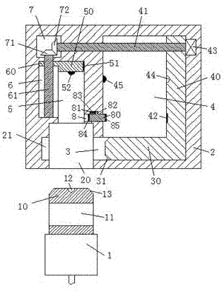
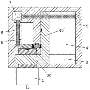
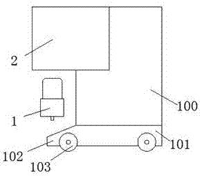
[0020] refer to Figure 1-3 As shown, a dust collector device of the present invention includes a base body 2 fixedly installed on the upper left side of the support frame 100 and a power transmission head 1 for cooperating with the base body 2, and the bottom end surface of the support frame 100 is fixedly installed with The base 101, the left end of the base 101 is provided with an inclined convex plate 102 extending to the left side, and the lower bottom surface of the base 101 is rollingly equipped with walking wheels 103, and the bottom end surface of the base 2 is provided with an insertion cavity 20, so The middle end of the right end wall...


PUM


Abstract

The invention discloses dust catcher equipment which comprises a equipment body fixedly mounted on the upper left side of a support frame and a power supply head used for fittingly connected with theequipment body. A base is fixedly mounted at the bottom end face of the support frame, the left end face of the base extends to the left side to form a sloping convex plate, walking wheels are mountedat the lower bottom surface of the base in a rolling manner, an inserting cavity is arranged in the bottom end face of the equipment body, a first sliding chute extending rightwards is arranged in the middle of the right end wall of the inserting cavity, and a second sliding chute communicated with the first sliding chute is arranged in the upper end wall of the first sliding chute. The power supply head firmly locked is safe in power, the power supply head is powered before locked during use, the power supply head is disconnected before unlocked when pulled out, and the entire equipment is easy and rapid to operate.

Description

technical field [0001] The invention relates to the technical field of dust collectors, in particular to dust collector equipment. Background technique [0002] Dust collectors are commonly used vacuuming equipment in people's daily life. Before using the dust collector, the power transmission head connected to it needs to be inserted into the power transmission seat. There is no locking device between the traditional power transmission head and the power transmission seat, so When accidentally touching the cable connected to the dust collector, the power transmission head will accidentally fall off from the power transmission base, resulting in interruption of power supply and affecting the use of the dust collector. It is easy to cause electric shock accidents when plugged in. Contents of the invention [0003] The technical problem to be solved by the present invention is to provide a dust collector device, which can solve the above-mentioned problems in the prior art....

Claims


Application Information

Patent Timeline
Patent Type & Authority Applications(China)
IPC IPC(8): H01R13/639H01R13/70H01R13/707
CPCH01R13/639H01R13/701H01R13/707
Inventor 王银露
Owner 王银露
Why Eureka
Try Eureka