2-magnetic-pole controller-free self-starting permanent magnet auxiliary synchronous reluctance motor

An auxiliary synchronous, reluctance motor technology, applied in the direction of magnetic circuit rotating parts, magnetic circuits characterized by magnetic materials, magnetic circuits, etc., can solve the problems of high cost, no self-starting operation function, etc., and achieve less usage , The effect of preventing the risk of high temperature demagnetization and reducing the cost of the system

Inactive Publication Date: 2018-05-04
WOLONG ELECTRIC GRP CO LTD
View PDF8 Cites 26 Cited by
  • Summary
  • Abstract
  • Description
  • Claims
  • Application Information

AI Technical Summary

Problems solved by technology

[0002] At present, the general reluctance motor needs to be equipped with a special controller to operate, and has no self-starting operation function. At

Method used


Image

  • 2-magnetic-pole controller-free self-starting permanent magnet auxiliary synchronous reluctance motor
  • 2-magnetic-pole controller-free self-starting permanent magnet auxiliary synchronous reluctance motor
  • 2-magnetic-pole controller-free self-starting permanent magnet auxiliary synchronous reluctance motor

Examples


Embodiment Construction

[0023] The technical solution of the present invention will be further described in detail below in conjunction with the accompanying drawings.

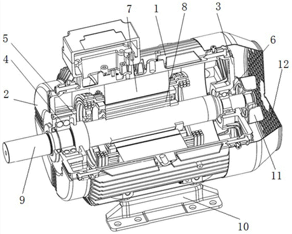
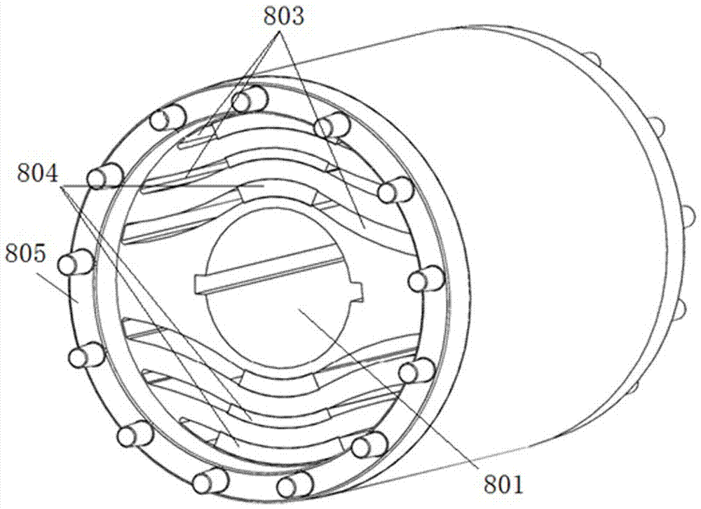
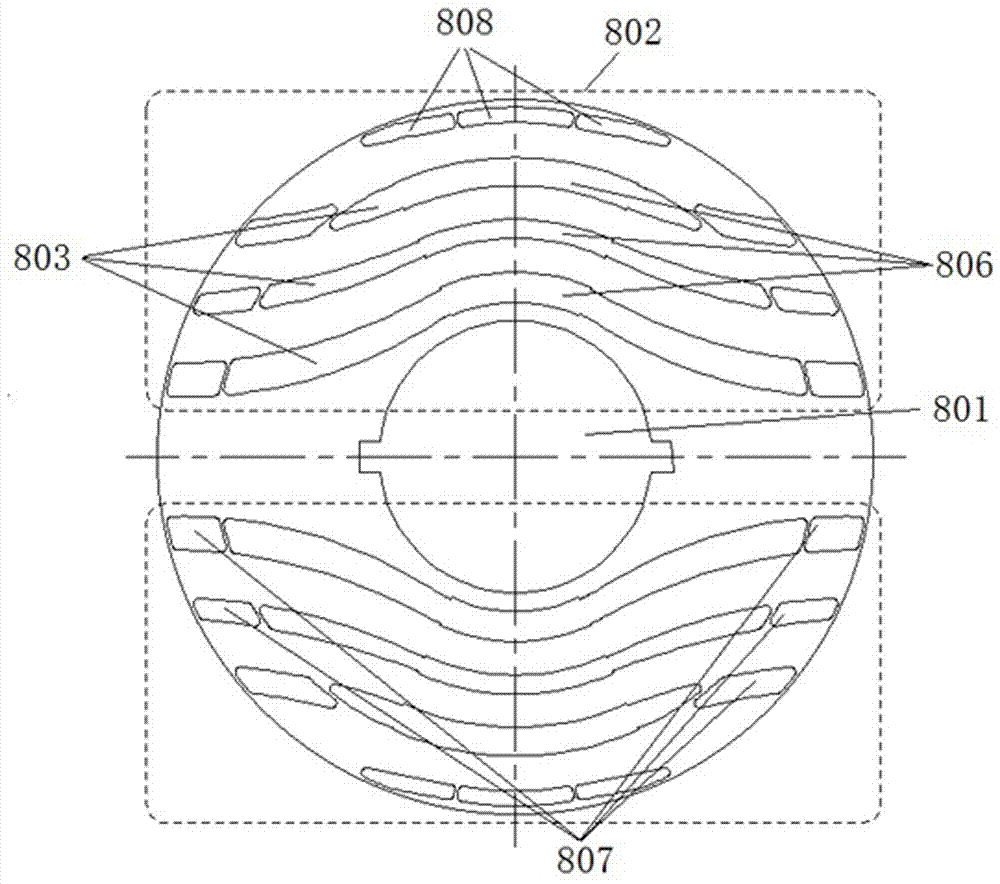
[0024] like Figure 1-3 As shown, a 2-pole non-controller self-starting permanent magnet assisted synchronous reluctance motor, including machine base 1, front end cover 2, rear end cover 3, front bearing 4, front bearing inner cover 5, rear bearing 6, rear bearing Inner cover, wire stator 7, rotor core 8, rotating shaft 9, feet 10, fan blades 11, wind cover 12, rotor core 8 is formed by stacking iron core punches with 2 magnetic poles 802, and iron core punches A rotating shaft hole 801 is provided in the center of the pole, and the two magnetic poles 802 include the same number of radially arranged reluctance slots 803, and a fan-shaped permanent magnet 804 is arranged in the middle of each reluctance slot 803; the rotor core 8 is located in the core punch A cast aluminum squirrel cage 805 is provided on the outer circumference of...


PUM


Abstract

The invention discloses a 2-magnetic-pole controller-free self-starting permanent magnet auxiliary synchronous reluctance motor, and relates to the field of the synchronous reluctance motor. At current, the reluctance motor can be only in operation by being equipped with a special controller, and needs a large number of rare earth permanent magnet material, so that the cost is high. The 2-magnetic-pole controller-free self-starting permanent magnet auxiliary synchronous reluctance motor comprises a machine base, a front end cover, a back end cover, a front bearing, a front bearing inner cover,a back bearing, a back bearing inner cover, a line stator, a rotor iron core, a rotary shaft, a bottom foot, a fan blade and a fan cover; the rotor iron core is formed by multiple iron core stampingsheets with two magnetic poles in an overlaying manner; rotary shaft holes are formed in the centers of the iron core stamping sheets; the two magnetic poles both comprise radially arranged reluctancegrooves of the same number; a fan-shaped permanent magnet is arranged in the middle of each reluctance groove; and an aluminum cast mouse cage is arranged on the periphery, on the outer sides of thereluctance grooves of the iron core stamping sheets, of the rotor iron core. By virtue of a combination of a permanent magnet synchronous motor and the synchronous reluctance motor in the technical scheme, and by combination of the aluminum cast mouse cage, use of a permanent magnet material is reduced, and high operation also can be realized without a controller, so that the motor cost is obviously lowered.

Description

technical field [0001] The invention relates to the field of synchronous reluctance motors, in particular to a 2-pole self-starting permanent magnet assisted synchronous reluctance motor. Background technique [0002] At present, the general reluctance motor needs to be equipped with a special controller to operate, and has no self-starting operation function. At the same time, for the general permanent magnet synchronous motor, a large amount of rare earth permanent magnet materials are used, resulting in high cost. Contents of the invention [0003] The technical problem to be solved and the technical task proposed by the present invention are to perfect and improve the existing technical solutions and provide a 2-pole self-starting permanent magnet assisted synchronous reluctance motor for the purpose of reducing costs. For this reason, the present invention takes the following technical solutions. [0004] A 2-pole non-controller self-starting permanent magnet assiste...

Claims


Application Information

Patent Timeline
IPC IPC(8): H02K1/27H02K1/02H02K3/04
CPCH02K1/2706H02K1/02H02K1/274H02K3/04
Inventor 胡吉亮严伟灿王国龙王斌孙军建
Owner WOLONG ELECTRIC GRP CO LTD
Why Eureka
Try Eureka