Rotor structure for improving irreversible demagnetization resisting capability of permanent magnets of permanent magnet motor

A technology of demagnetization ability and rotor structure, applied in the magnetic circuit shape/style/structure, magnetic circuit rotating parts, magnetic circuit and other directions, can solve the problem of unstable motor performance, motor performance changes, unable to restore to the initial state, etc. problem, to achieve the effect of improving the resistance to irreversible demagnetization and ensuring the output performance

Active Publication Date: 2018-05-04
SOUTHEAST UNIV
View PDF5 Cites 5 Cited by
  • Summary
  • Abstract
  • Description
  • Claims
  • Application Information

AI Technical Summary

Problems solved by technology

For permanent magnets that work in the nonlinear section, after removing the demagnetizing magnetic field, the permanent magnets will run along the new recovery line and cannot return to the original initial state, resulting in irreversible changes in the performance of

Method used


Image

  • Rotor structure for improving irreversible demagnetization resisting capability of permanent magnets of permanent magnet motor
  • Rotor structure for improving irreversible demagnetization resisting capability of permanent magnets of permanent magnet motor
  • Rotor structure for improving irreversible demagnetization resisting capability of permanent magnets of permanent magnet motor

Examples


Embodiment Construction

[0017] The technical solution of the present invention will be further introduced below in combination with specific implementation methods and accompanying drawings.

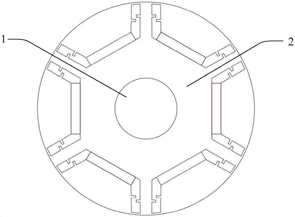
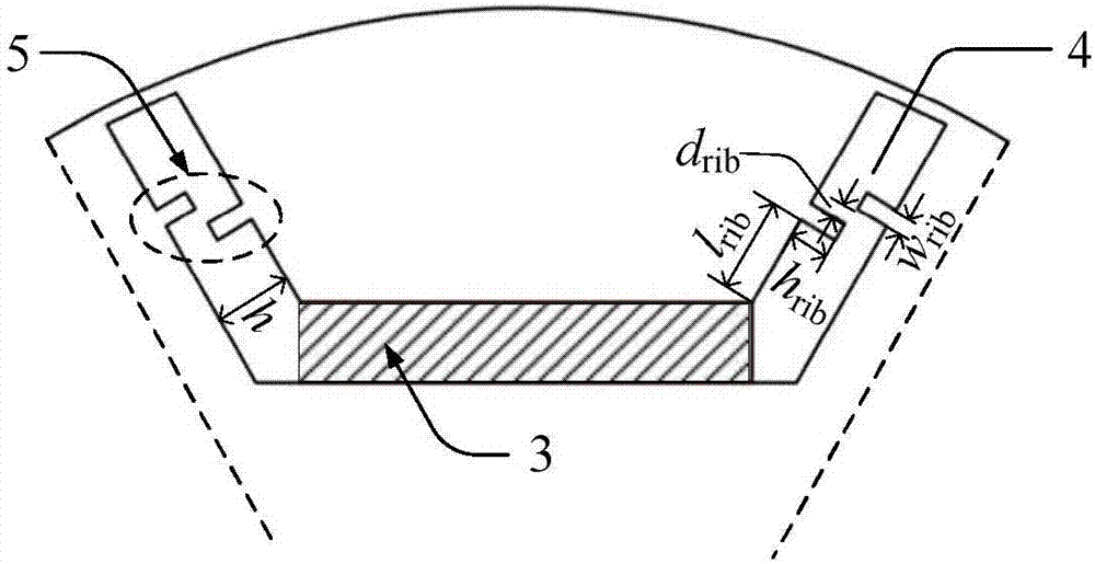
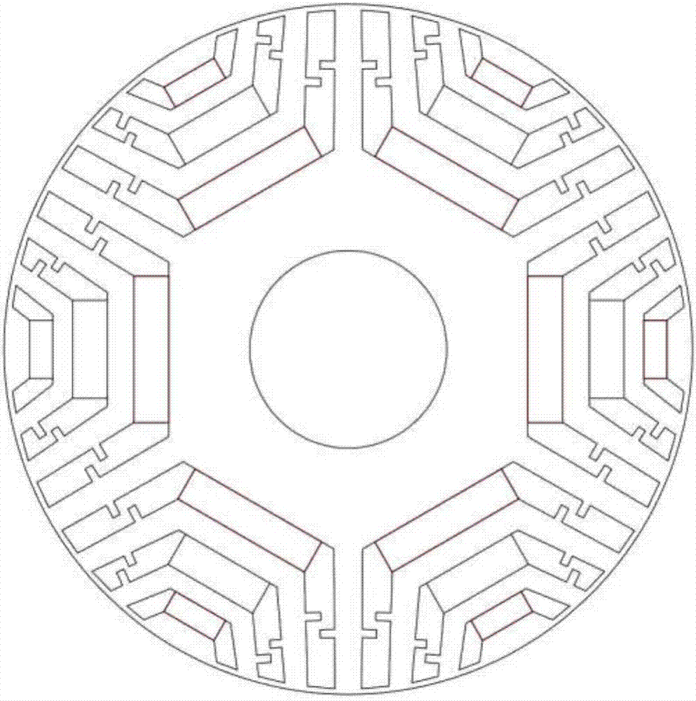
[0018] This specific embodiment discloses a rotor structure that improves the irreversible demagnetization resistance of permanent magnet motors, such as figure 1 As shown, it includes a central rotating shaft 1 and a rotor core 2, and the central rotating shaft 1 and the rotor core 2 are installed on the same central axis. Such as figure 2 As shown, around the central axis, a plurality of U-shaped through-slots 4 of the same shape and size are uniformly arranged on the rotor core 2, and the bottom of the U-shaped through-slot 4 is provided with a permanent magnet 3, and the U-shaped through-slot 4 There are several magnetic bridges 5 that are not connected to each other on the two sides of the tank. Because the magnetic bridges 5 are not connected, the magnetic bridges 5 are also called bypass magnetic brid...


PUM


Abstract

The invention discloses a rotor structure for improving irreversible demagnetization resisting capability of permanent magnets of a permanent magnet motor. The rotor structure comprises a central rotating shaft and a rotor core, wherein the central rotating shaft and the rotor core are mounted by sharing the central axis. Around the central axis, a plurality of U-shaped through grooves identical in shape and size are formed in the rotor core evenly. The permanent magnets are arranged at bottom groove bodies of the U-shaped through grooves. A plurality of non-communicated magnetic bridges are arranged on lateral groove bodies of the U-shaped through grooves. The rotor structure has the advantages that magnetic bridge structures, not completely communicated with one another, are arranged onthe lateral groove bodies of the U-shaped through grooves, and accordingly, the irreversible demagnetization resisting capability of the motor is improved effectively; torque output capacity of the motor is not influenced by the magnetic bridge structures obviously, and accordingly, output performance of the motor is guaranteed.

Description

technical field [0001] The invention relates to the field of permanent magnet motors, in particular to a rotor structure for improving the irreversible demagnetization resistance of permanent magnets of permanent magnet motors. Background technique [0002] In the permanent magnet motor, there are permanent magnets distributed in the rotor iron core according to certain rules, and the magnetic field established by the permanent magnets interacts with the magnetic field of the stator armature to generate electromagnetic torque. When the motor speed increases, the counter electromotive force induced by the permanent magnetic field in the armature winding also increases. In order to further increase the speed, the usual method is to use the excitation component of the armature current to generate a demagnetization magnetic field to perform field weakening control. , that is, to apply a demagnetizing magnetic field to the permanent magnet. In some special cases, such as when st...

Claims


Application Information

Patent Timeline
IPC IPC(8): H02K1/27H02K1/28
CPCH02K1/274H02K1/28H02K2213/03
Inventor 林明耀孔永乐伟伍锡坤
Owner SOUTHEAST UNIV
Why Eureka
Try Eureka