Motor rotor punch and permanent magnet motor
A motor rotor and punching technology, applied in the field of permanent magnet motors, can solve the problems of reduced output torque, reduced utilization of magnetic steel, increased motor costs, etc., and achieves the effect of reducing manufacturing costs
- Summary
- Abstract
- Description
- Claims
- Application Information
AI Technical Summary
Problems solved by technology
Method used
Image
Examples
no. 1 example
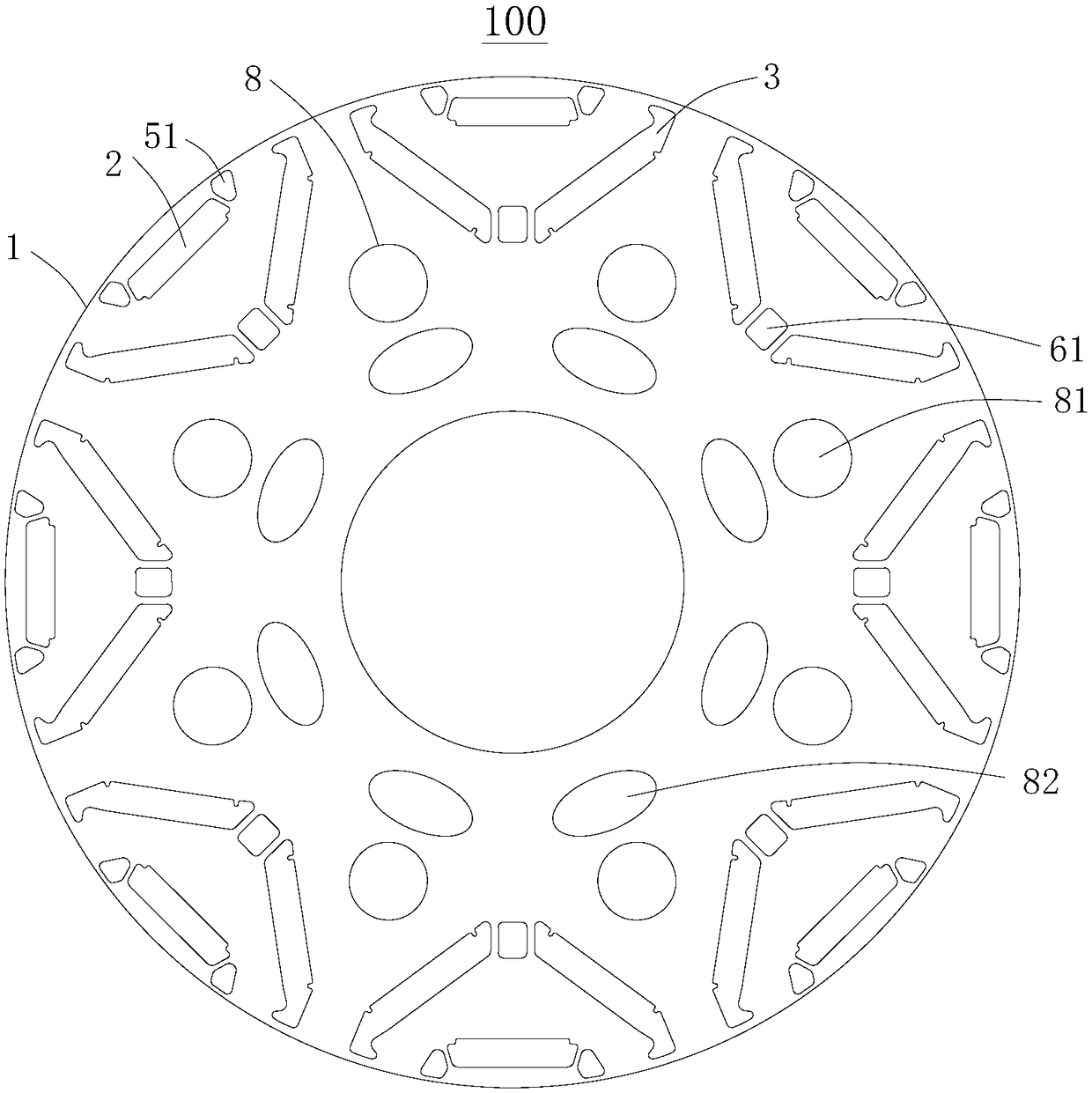
[0034] Please refer to figure 1 , this embodiment provides a motor rotor punching plate 100 , which is applied to new energy electric vehicles, and includes a punching plate body 1 .
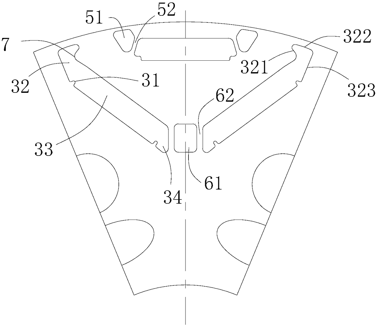
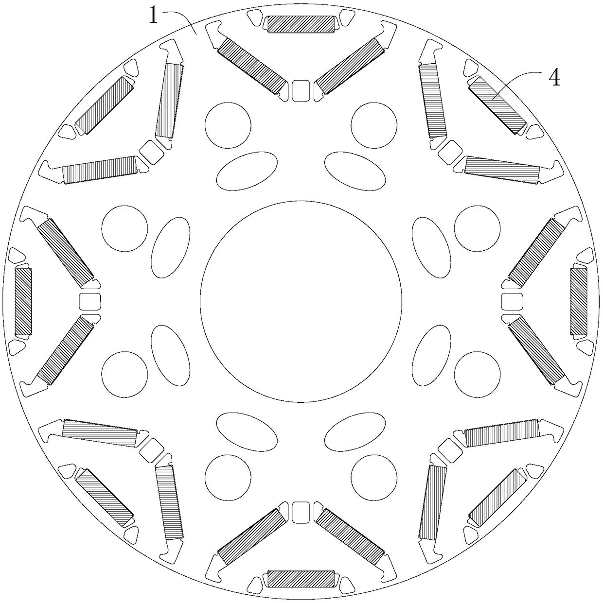
[0035] In this embodiment, there are multiple groups of magnetic steel groove groups evenly distributed in the circumferential direction of the punching body 1, and each group of magnetic steel groove groups includes a first magnetic steel groove 2 and two second magnetic steel grooves 3, and two second magnetic steel groove groups The magnetic steel grooves 3 are symmetrically distributed in a V shape along the center line of the first magnetic steel groove 2, and the tip of the V shape faces the center of the punch body 1, and the first magnetic steel groove 2 is located at the opening end of the V shape. Both ends of the length direction of the magnetic steel groove 2 are symmetrically provided with two first magnetic shielding air grooves 51, which limit the magnetic flux leakage magnetic fl...
no. 2 example
[0051] After research, the researchers found that the motor rotor stamping 100 provided by the present invention, on the basis of the above-mentioned first embodiment, can also make the following optional other structural solutions, which are specifically described as follows:
[0052] Such as Figure 4 As shown, in this embodiment, there are two magnetically permeable protrusions 7 , one of which is located on the first connecting edge 321 , and the other is located on the third connecting edge 323 . It is equivalent to two magnetically conductive protrusions 7 arranged opposite to each other, which is convenient for guiding the magnetic force lines to pass through the first groove segment 32 .
no. 3 example
[0054] This embodiment provides a permanent magnet motor, including the above-mentioned motor rotor stamping 100 .
[0055] In this embodiment, the above-mentioned motor rotor stamping 100 is applied to the permanent magnet motor, which improves the irreversible demagnetization resistance of the motor, reduces the cost of the permanent magnet, reduces the manufacturing cost of the permanent magnet motor, and meets the needs of users .
PUM
 Abstract
Description
Claims
Application Information
 - R&D
- Intellectual Property
- Life Sciences
- Materials
- Tech Scout
- Unparalleled Data Quality
- Higher Quality Content
- 60% Fewer Hallucinations
Browse by: Latest US Patents, China's latest patents, Technical Efficacy Thesaurus, Application Domain, Technology Topic, Popular Technical Reports.
© 2025 PatSnap. All rights reserved.Legal|Privacy policy|Modern Slavery Act Transparency Statement|Sitemap|About US| Contact US: help@patsnap.com


