Clamping force-adjustable tangential driving type rotary inertial piezoelectric actuator and method

A piezoelectric actuator and driving technology, applied in piezoelectric effect/electrostrictive or magnetostrictive motors, electrical components, generators/motors, etc. Inability to act, etc., to achieve the effect of infinite stroke, stable performance, and reliable clamping

Inactive Publication Date: 2018-05-04
XI AN JIAOTONG UNIV
View PDF6 Cites 10 Cited by
  • Summary
  • Abstract
  • Description
  • Claims
  • Application Information

AI Technical Summary

Problems solved by technology

[0004] Inertial piezoelectric actuators generally adopt asymmetric signal, asymmetric mechanical clamping or asymmetric friction design, and drive through inertial impact; structures using asymmetric mechanical clamping and asymmetric friction design are generally Large size, complex design, and difficult assembly; commonly used asymmetric signal control mechanisms are simple in structure and easy to implement, but after this type of structure is assembled, the contact surface between the drive mechanism and the motion mechanism will be lost due to friction and gradually reduce The precision of the actuator even makes it impossible to actuate

Method used


Image

  • Clamping force-adjustable tangential driving type rotary inertial piezoelectric actuator and method
  • Clamping force-adjustable tangential driving type rotary inertial piezoelectric actuator and method
  • Clamping force-adjustable tangential driving type rotary inertial piezoelectric actuator and method

Examples


Embodiment Construction

[0021] The present invention will be described in further detail below in conjunction with the accompanying drawings and specific embodiments.

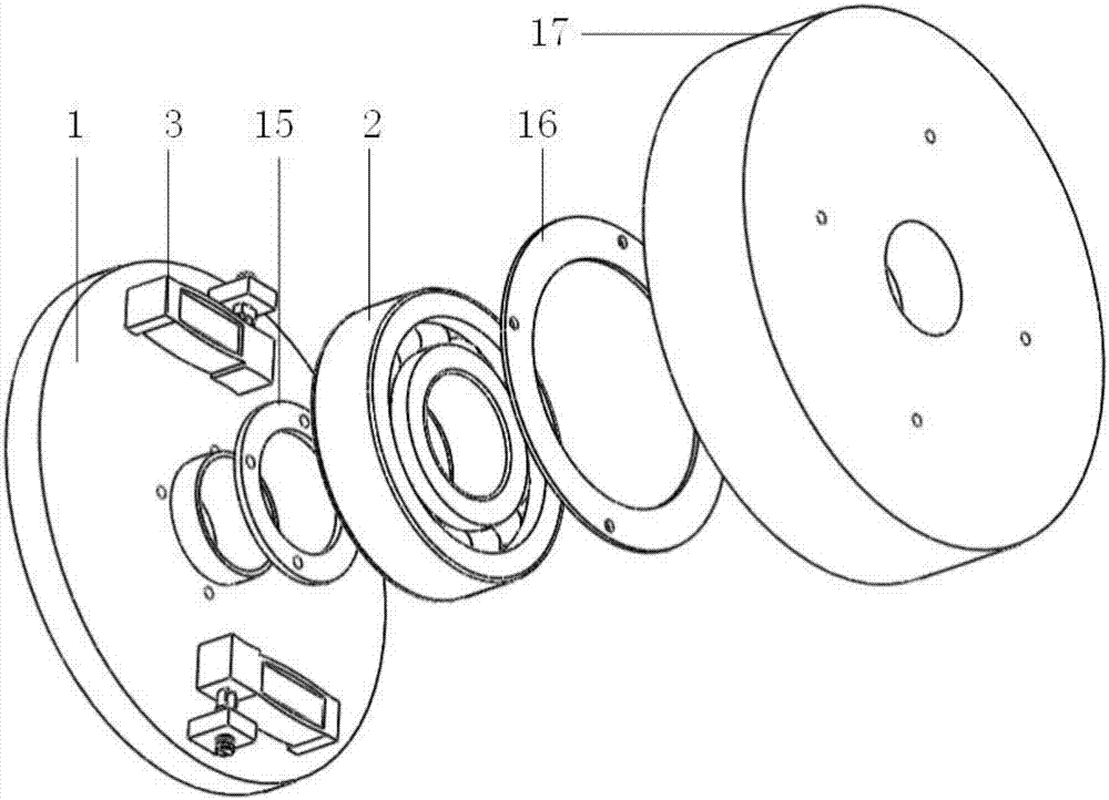
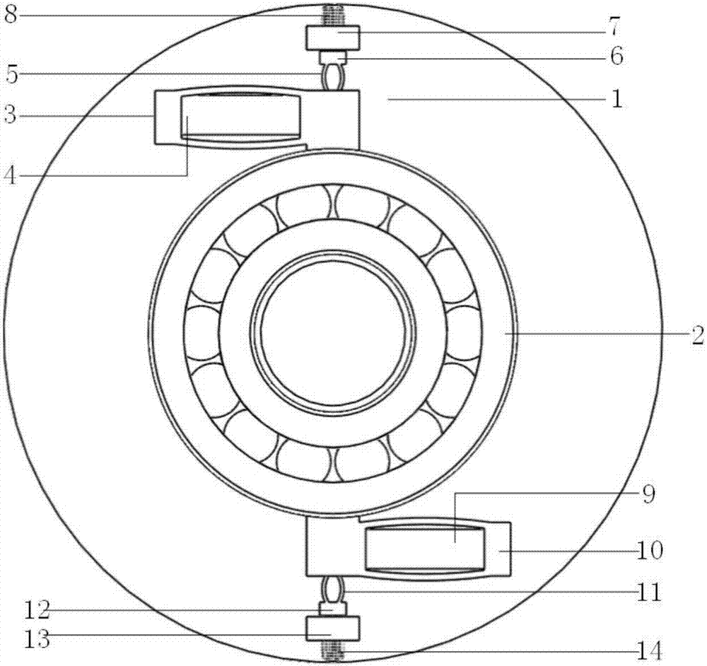
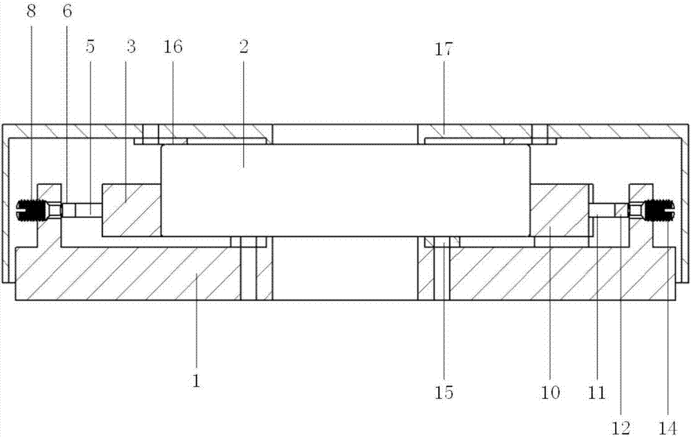
[0022] Such as figure 1 , figure 2 and image 3 As shown, the clamping force adjustable tangentially driven rotary inertial piezoelectric actuator of the present invention, the main parts include base 1, bearing 2, housing 17 and two anti-symmetrically arranged driving mechanisms, the whole structure has rotational symmetry The inside contains through holes; the inner ring gasket 15 is bonded to the inner ring of the bearing 2 and fixed to the base 1 by screws; the outer ring of the bearing 2 is bonded to the outer ring gasket 16, and the outer ring gasket 16 passes through The screw and the housing 17 are fixed; the two anti-symmetrically arranged driving mechanisms include the first rhombic ring 3 and the second rhombic ring 10 and the first compression rings respectively installed in the first rhombic ring 3 and the second rhomb...


PUM


Abstract

The invention provides a clamping force-adjustable tangential driving type rotary inertial piezoelectric actuator and a method. The actuator is composed of a base, a bearing, a piezoelectric stack, arhombic ring, an elastic element, a bearing gasket and a screw, wherein the bearing gasket and the screw are required for assembly and adjustment. A rhombic ring driving mechanism drives the bearing to rotate through the outer ring of the bearing fixed on the base by means of a friction inner ring. The outer ring of the bearing is connected with a shell through the bearing gasket so as to output the rotating motion. The friction force between a rhombic ring friction block and the outer ring of the bearing is a clamping force. The elastic element is extruded by adjusting the screw so as to generate the deformation. Through changing the positive pressure between the rhombic ring friction block and the outer ring of the bearing, the clamping force can be adjusted. Through arranging strain gauges on the surface of the elastic element, the size of the clamping force of the actuator can be accurately obtained. According to the invention, the bearing is driven to rotate in the tangential direction, and the function of measuring and adjusting the clamping force is realized. A through hole is formed in the structure, and the clamping force-adjustable tangential driving type rotary inertialpiezoelectric actuator has important application in the field of optics. The clamping force-adjustable tangential driving type rotary inertial piezoelectric actuator is compact in structure and easy to assemble. The clamping force-adjustable tangential driving type rotary inertial piezoelectric actuator has the advantages of high resolution, infinite travel and stable actuation performance.

Description

technical field [0001] The invention belongs to the technical field of inertial piezoelectric actuators, and in particular relates to a rotary inertial piezoelectric actuator with adjustable clamping force and a tangentially driven through hole, and an actuating method. Background technique [0002] The piezoelectric drive has the advantages of small size, high precision, high frequency response, no heat generation, and easy control; the inertial piezoelectric actuator is based on the principle of friction and inertial impact, and can continuously output the tiny single-step displacement of the piezoelectric stack. At the same time, it has the advantages of high precision and large stroke. [0003] Inertial piezoelectric drives have been widely used in nanoscale high-precision linear positioning mechanisms, high-precision rotary platforms, micro-robots, multi-degree-of-freedom drives and other fields; however, traditional actuators are generally solid structures without thro...

Claims


Application Information

Patent Timeline
Patent Type & Authority Applications(China)
IPC IPC(8): H02N2/10H02N2/12
CPCH02N2/101H02N2/12
Inventor 王源徐明龙邵妍肖瑞江韩文文
Owner XI AN JIAOTONG UNIV
Why Eureka
Try Eureka