Rotating base of industrial robot

A technology of industrial robots and rotating bases, applied in manipulators, manufacturing tools, program-controlled manipulators, etc., can solve the problems of inability to cool down and clean up the gaps and debris, and achieve the effect of ensuring clean and hygienic

Inactive Publication Date: 2018-05-08
GUANGXI RUIKE IND ROBOT CO LTD
View PDF4 Cites 14 Cited by
  • Summary
  • Abstract
  • Description
  • Claims
  • Application Information

AI Technical Summary

Problems solved by technology

[0004] The purpose of the present invention is to provide a rotating base of an industrial robot

Method used


Image

  • Rotating base of industrial robot
  • Rotating base of industrial robot
  • Rotating base of industrial robot

Examples


Embodiment 1

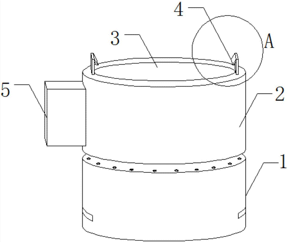
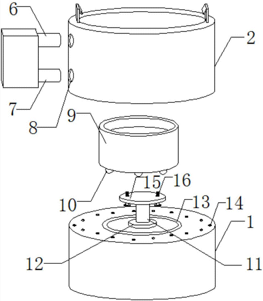
[0023] see Figure 1-4 As shown, a rotating base of an industrial robot includes a fixed base 1 and a support base 2. A slot 3 is provided inside the support base 2 to engage the bottom of the industrial robot. Both sides of the top of the support base 2 are welded with buckles. 4, and the buckle 4 is engaged with the side wall of the robot to ensure the stability of the robot. The side wall of the support seat 3 is provided with a water tank 5, and the water tank 5 is filled with cooling liquid. The bottom is provided with a water inlet pipe 7, and one end of the water inlet pipe 6 and the water inlet pipe 7 is engaged in the clamping hole 8, and the bottom of the support seat 2 is welded with a support frame 9 to support and fix the support seat 2, and the bottom of the support frame 9 is engaged with a number of balls 10 , and the bottom of the ball 10 is engaged in the chute 13, and can slide in the chute 13, the middle part of the fixed seat 1 is engaged with the rotating...

Embodiment 2

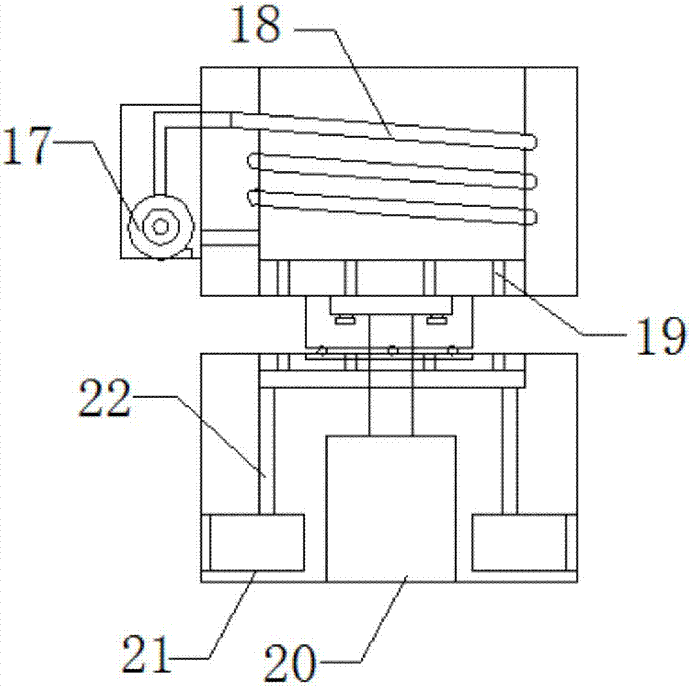
[0025] In addition, please continue to Figure 2-4 As shown, the difference between it and Embodiment 1 is that the support seat 2 is arranged directly above the fixed seat 1, and the support seat 2 has a cylindrical structure, so that the base can be fixed more stably and firmly, ensuring that the base can rotate and work, and the fixed The bottom plate 15 is fastened to the bottom of the support base 2 through bolts 16, and the fixed base plate 15 is arranged in the middle of the support frame 9, so that the fixed plate 15 can be firmly engaged and fixed on the bottom of the support base 2 to ensure the stability of the support base 2 , one end of several balls 10 is engaged in the bottom of the fixed frame 9, the other end is engaged in the chute 13, and the balls 10 and the chute 13 are rotationally connected, so that the balls 10 can slide in the chute 13, which is convenient for the support seat 2 Rotate to adjust the position, the water pump 17, the motor 20, and the ex...


PUM


Abstract

The invention discloses a rotating base of an industrial robot. The rotating base of the industrial robot comprises a fixing seat, a supporting seat, a clamping groove, buckles, a water tank, a wateroutlet pipe, a water inlet pipe, a clamping hole, a supporting frame, balls, a rotating shaft, a bearing, a sliding groove, vent holes, a fixed base plate, bolts, a water pump, a cooling pipe, a ventilation groove, a motor, an exhaust fan and a guide pipe. The rotating base of the industrial robot has the beneficial effects that the water pump is arranged in the water tank, the water pump is connected with the cooling pipe through the water inlet pipe, so that the water pump can be used for pumping cooling liquid in the water tank into the cooling pipe, the cooling pipe tightly attached to theouter wall of the clamping groove is used for cooling the clamping groove, and it can be avoided that high heat energy generated by long-time work damages electric appliance components; the exhaust fan is arranged in the fixing seat, so that external air can be sucked through the exhaust fan and enters the clamping groove through the vent holes and the ventilation groove, and upwards moving airflow blows waste clamped into a gap between the clamping groove and a robot body out.

Description

technical field [0001] The invention relates to a rotating base, in particular to a rotating base of an industrial robot, and belongs to the technical field of industrial robot accessory equipment application. Background technique [0002] An industrial robot is a multi-joint manipulator or a multi-degree-of-freedom machine device for the industrial field. It can perform work automatically and is a machine that realizes various functions by its own power and control capabilities. It can be commanded by humans or run according to pre-programmed programs. Modern industrial robots can also act according to the principles and programs formulated by artificial intelligence technology. The rotating base of the industrial robot is a supporting and fixing device arranged at the bottom of the industrial robot, and can rotate to adjust the position of the industrial robot. [0003] However, the existing rotating base still has certain defects in use. Although the existing rotating ba...

Claims


Application Information

Patent Timeline
IPC IPC(8): B25J9/00B25J19/00
CPCB25J9/0009B25J19/0054B25J19/0058
Inventor 黄庚保
Owner GUANGXI RUIKE IND ROBOT CO LTD
Why Eureka
Try Eureka