An injection mold opening and closing control mechanism in shoe molding equipment

A molding equipment and injection mold technology, applied in the field of machinery, can solve the problems of complex hydraulic system structure, inconvenient processing, affecting control accuracy, etc., and achieve the effect of strengthening mold clamping effect, improving stability and quality, and reducing manufacturing cost.

Active Publication Date: 2019-12-03
台州市乐图进出口有限公司
View PDF7 Cites 0 Cited by
  • Summary
  • Abstract
  • Description
  • Claims
  • Application Information

AI Technical Summary

Problems solved by technology

[0005] There is a problem with the above-mentioned molding machine: the injection mold is opened and closed by hydraulic means, and each injection mold needs to be equipped with an independent hydraulic pipeline, which makes the structure of the entire hydraulic system more complicated, which is not convenient for processing. It also affects the control accuracy

Method used


Image

  • An injection mold opening and closing control mechanism in shoe molding equipment
  • An injection mold opening and closing control mechanism in shoe molding equipment
  • An injection mold opening and closing control mechanism in shoe molding equipment

Examples


Embodiment 1

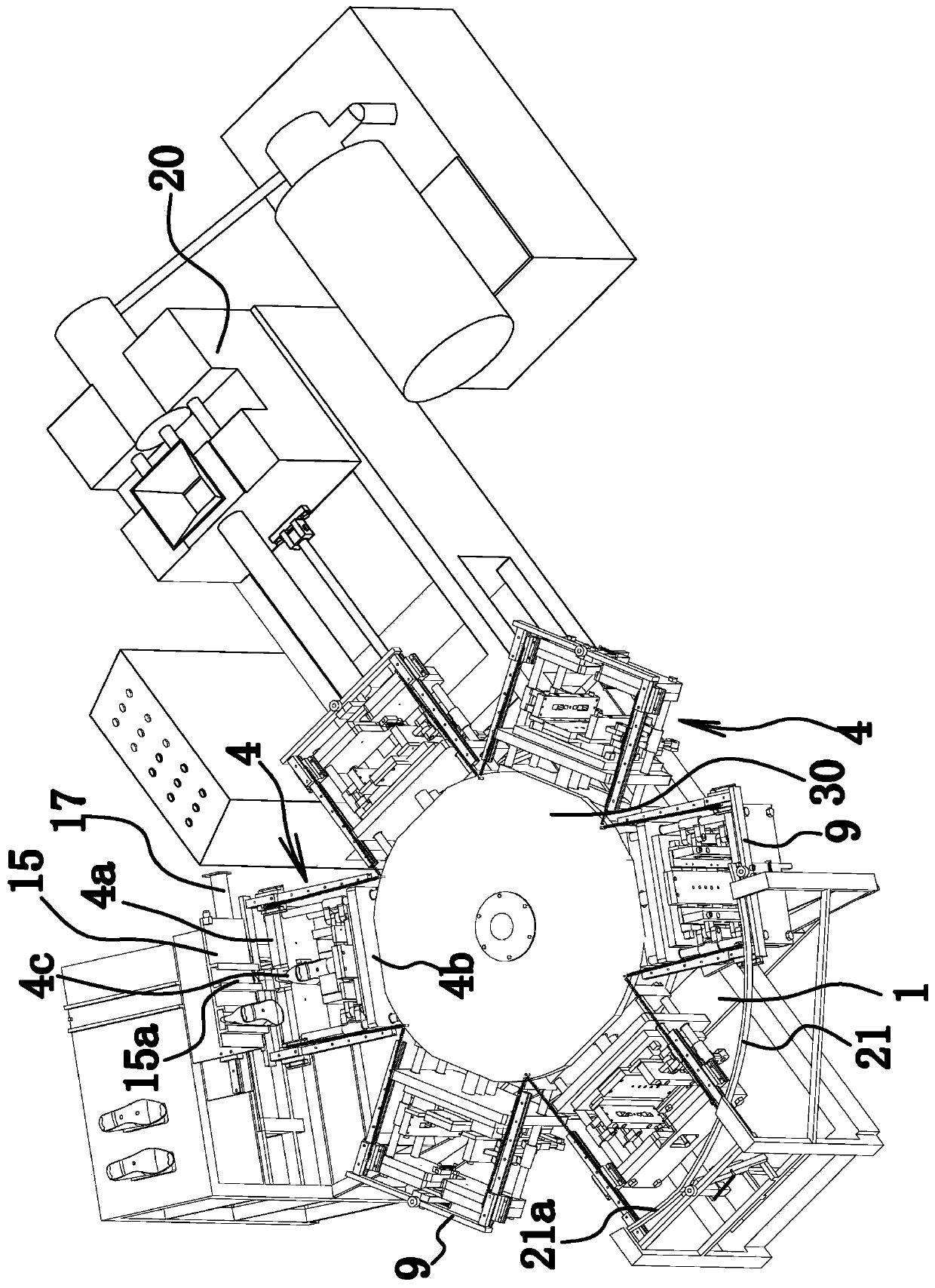
[0028] like figure 1 As shown, the shoe forming equipment is composed of a frame 1, a turntable 2, a motor 3, an injection mold 4, a shoe last changing mechanism, an injection molding mechanism 20, a material removing head mechanism, a control mechanism and the like.

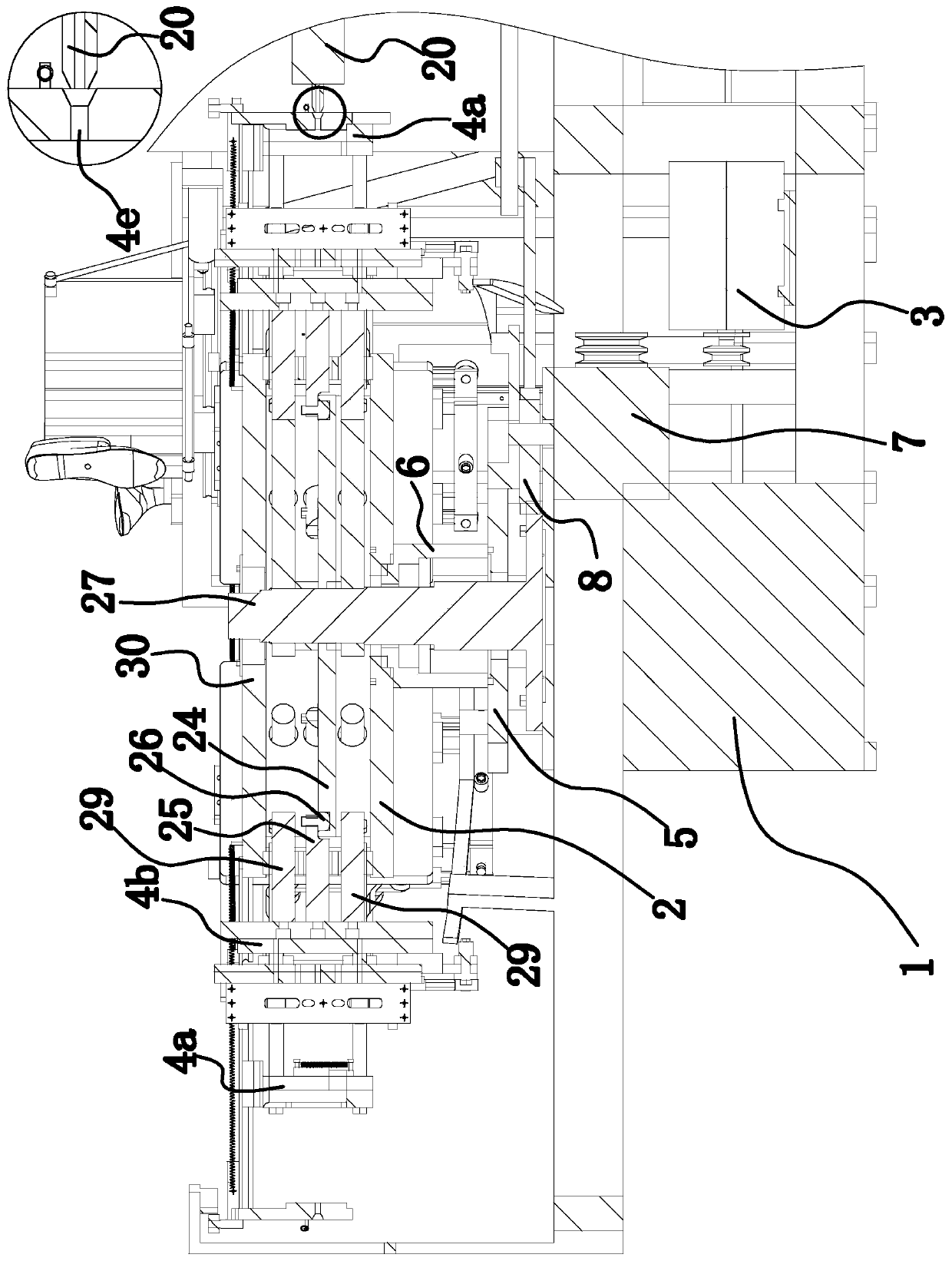
[0029] Wherein, the turntable 2 is disc-shaped and arranged on the frame 1 along the horizontal direction, and the turntable 2 is rotatably connected with the frame 1 through a rotating shaft 6 . The motor 3 is installed on the frame 1 and can drive the turntable 2 to rotate around the axis. Specifically, as figure 2 As shown, the pinion gear 5 is fixed on the rotating shaft 6, the gearbox 7 is fixed on the frame 1, the main shaft of the motor 3 is connected with the input shaft of the gearbox 7 through a synchronous belt transmission structure or a gear transmission structure, and the output shaft of the gearbox 7 The main gear 8 is fixed on the top, and the main gear 8 and the auxiliary gear 5 are meshed, s...

Embodiment 2

[0052] The structure and principle of the second embodiment are basically the same as those of the first embodiment, except that the driving member 21 is the first cylinder fixed on the frame 1, and the piston rod of the first cylinder is opposite to the guide block 9.

Embodiment 3

[0054] The structure and principle of the present embodiment three are basically the same as those of the first embodiment, except that the separating part 22 is the cylinder two fixed on the frame 1, and the piston rod of the cylinder two can offset the rubber block two 4g to drive the rubber block. Block two 4g overcome the elastic force rotation of spring one 10.


PUM


Abstract

The invention provides an opening and closing control mechanism for an injection mold of shoe forming equipment, and belongs to the technical field of machines. The shoe forming equipment comprises arack, a rotary disc rotatably arranged on the rack, and the injection mold fixedly arranged on the edge of the rotary disc. The injection mold comprises an upper mold base and a lower mold base fixedly connected with the rotary disc. A shoe tree changing mechanism, an injection molding mechanism and a material end removing mechanism are sequentially arranged on one side of the rotary disc in the rotating direction of the rotary disc. A disc body right facing the rotary disc is fixed to the rack. A driving shaft is fixed to the lower mold base. A control mechanism comprises an annular groove formed in the disc body and a driving block arranged in the annular groove and capable of sliding along the annular groove, and the driving block is fixedly connected with the driving shaft. The annulargroove is composed of a first arc-shaped guide section, a second arc-shaped section and a third arc-shaped section, and the first guide section, the second guide section and the third guide section are sequentially arranged in the rotating direction of the rotary disc. The opening and closing control mechanism for the injection mold of the shoe forming equipment has the advantage of being simplein structure.

Description

technical field [0001] The invention belongs to the technical field of machinery, and relates to shoe molding equipment, in particular to an injection mold opening and closing control mechanism in the shoe molding equipment. Background technique [0002] At present, the combination of shoe body and sole in shoes such as rubber shoes and plastic shoes is generally realized through injection molds. Existing injection molds generally include an upper mold base, a lower mold base, a bottom mold fixed on the lower mold base, a clamping mold and a shoe tree between the upper mold base and the bottom mold. Wherein, the shoe last, the clamping mold and the bottom mold surround to form an injection molding cavity, and the bottom mold is provided with a glue inlet communicating with the bottom mold cavity. [0003] During injection molding, the injection molding machine injects plastic into the injection cavity through the plastic inlet to complete the integral molding of the shoe bo...

Claims


Application Information

Patent Timeline
Patent Type & Authority Patents(China)
IPC IPC(8): B29C45/06B29C45/66B29L31/50
CPCB29C45/06B29C45/66B29L2031/50
Inventor 郑能明
Owner 台州市乐图进出口有限公司
Why Eureka
Try Eureka