
A Straw Gas Purification System

A technology of gas purification and straw, which is applied in the field of pyrolysis gas purification process, can solve the problems of large equipment resistance, cumbersome process flow, and inapplicable gas purification, etc., to achieve physical and mental health, short process, and small footprint Effect

Active Publication Date: 2019-11-08
WUHAN JINZHONG PETROCHEM ENG
View PDF5 Cites 0 Cited by
  • Summary
  • Abstract
  • Description
  • Claims
  • Application Information

AI Technical Summary

Problems solved by technology

[0005] Therefore, the technical problem to be solved by the present invention is to overcome the cumbersome technological process of the straw purification process in the prior art, and it is not suitable for the micro-positive pressure state produced by the rotary carbonization furnace due to the large resistance of its equipment. The defects of gas purification, thus providing a straw gas purification system

Method used


Image

  • A Straw Gas Purification System
  • A Straw Gas Purification System
  • A Straw Gas Purification System

Examples


Embodiment 1

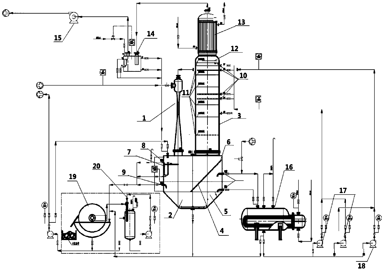
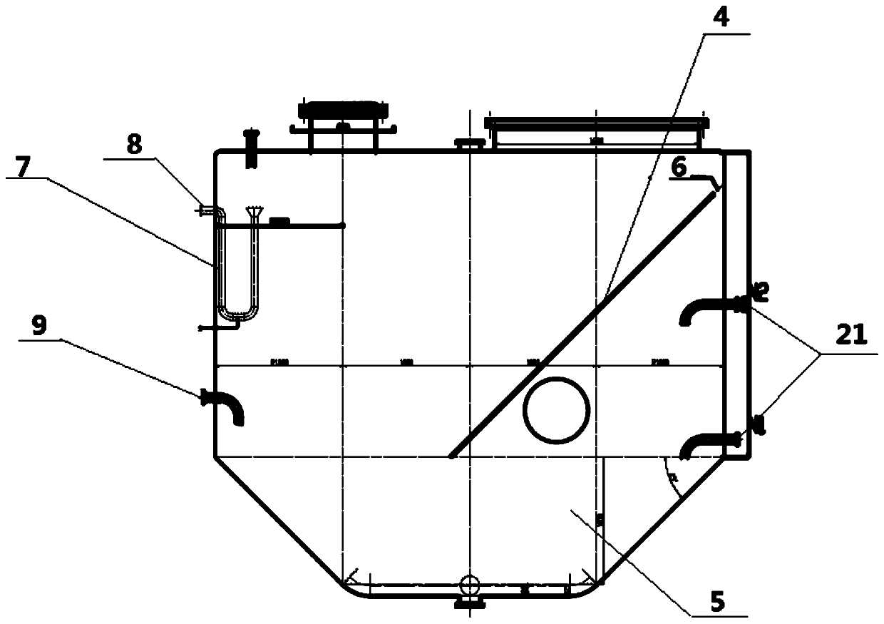
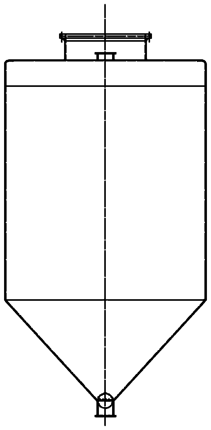
[0044] This embodiment provides a straw gas purification system, such as Figure 1-6 As shown, the straw gas purification system includes:

[0045] The ejector 1 is used to fully mix the high-temperature straw gas with the washing liquid, pressurize it, and then output;

[0046] The sedimentation separation tank 2 is used for gas-liquid separation and output of the straw gas scrubbing liquid mixture output from the ejector 1;

[0047] The spray washing tower 3 is used to purify and wash the gas separated from the settling separation tank 2;

[0048] The settling separation tank 2 is located below the ejector 1 and the spray washing tower 3, and the inlet end and the outlet end of the settling separation tank 2 are respectively connected to the bottom outlet end of the ejector 1 and The bottom inlet end of the spray scrubber 3 is described.

[0049] The sedimentation separation tank 2 is a closed cone-column design, and the sedimentation separation tank 2 is divided into an upper and l...

Embodiment 2

[0062] The high-temperature straw gas from the straw vaporization furnace is fully mixed with the scrubbing liquid under the drive of the ejector and enters the sedimentation separation tank after the temperature is reduced. After the gas-liquid separation, the gas enters the spray scrubber at the bottom, and is condensed at the top of the tower. It is discharged into the liquid sealing tank at the top of the tower, and sent to the straw carbonization furnace as fuel gas through the straw gas induced draft fan;

[0063] The liquid after gas-liquid separation stays in the sedimentation separation tank for about 15 minutes to allow wood tar and entrained dust to settle and layer. The wood vinegar is completely miscible with water, and the floating matter is discharged from the upper part of the liquid layer. It is discharged from the bottom of the tank into the rotary drum vacuum filter, the filter residue after suction filtration, namely the mixture of wood tar and dust, is sent ou...


PUM


Abstract

The invention discloses a straw gas purifying system, and belongs to the technical field of pyrolysis gas purifying technology. The straw gas purifying system comprises an injector, a settling separation tank, and a spray scrubbing tower; the injector is used for full mixing of high temperature straw gas with washing liquid, and pressurized output; the settling separation tank is used for gas liquid separation and output of a straw gas washing liquid mixture output from the injector; the spray scrubbing tower is used for purifying and separating gas obtained via separation from the settling separation tank; the settling separation tank is arranged below the injector and the spray scrubbing tower; an input end and an output end of the settling separation tank are communicated with the bottom output end of the injector and the bottom input end of the spray scrubbing tower. The process flow of the straw gas purifying system is simple, and the straw gas purifying system is especially suitable for purifying of straw gas from rotary carbonizing furnaces under micro-positive pressure.

Description

Technical field [0001] The invention relates to the field of purification technology of pyrolysis gas, in particular to a straw gas purification system. Background technique [0002] At present, as an effective way to utilize biomass resources on a large scale, biomass dry distillation technology has received more and more attention from the society. The existing biomass dry distillation technology generally includes pyrolysis furnace, cooler, gas-liquid separator, tar adsorber and gas storage tank. However, the biomass gas produced, such as straw gas, usually contains a lot of impurities, such as dust, wood tar, wood vinegar, and water, which will not only reduce the heat generated during combustion, but also cause the burner to block Other accidents will affect the stable operation of the device. [0003] To this end, Chinese patent document CN2698791Y discloses a biomass dry distillation carbonization gasification device, including a dry distillation furnace, a heavy tar separ...

Claims


Application Information

Patent Timeline
Patent Type & Authority Patents(China)
IPC IPC(8): C10K1/02C10K1/08
CPCC10K1/02C10K1/08
Inventor 李廷均徐清武郭奇志易金华
Owner WUHAN JINZHONG PETROCHEM ENG
Learn More