Furnace body in cooling section of industrial reaction furnace

A technology of industrial reaction and cooling section, which is applied in the direction of furnaces, furnace components, furnace cooling devices, etc., and can solve problems such as large amount of coolant usage, low cooling efficiency, and complex structure of the furnace body in the cooling section

Active Publication Date: 2019-04-26
海盐鸳鸯丝绸印染股份有限公司
View PDF7 Cites 0 Cited by
  • Summary
  • Abstract
  • Description
  • Claims
  • Application Information

AI Technical Summary

Problems solved by technology

[0003] In the prior art, the cooling and cooling section in some industrial reactors mostly takes away heat through water cooling. The structure of the cooling section is relatively complicated, and the cooling efficiency is not high due to the large amount of coolant used.

Method used


Image

  • Furnace body in cooling section of industrial reaction furnace

Examples


Embodiment Construction

[0015] The present invention will be further described below in conjunction with the accompanying drawings and specific embodiments.

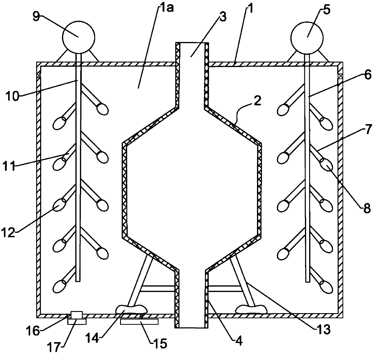
[0016] Please refer to the attached figure 1 As shown, the present invention provides a furnace body in the cooling section of an industrial reaction furnace, comprising an outer furnace body 1 with a cooling chamber 1a, a cooling furnace body 2 is arranged in the cooling chamber 1a, and the top of the cooling furnace body 2 passes through an upper through pipe 3 Pass through the outer furnace body 1 to communicate with the outside, and the bottom of the cooling furnace body 2 passes through the outer furnace body 1 to communicate with the outside through the lower through pipe 4; the top outer wall of the outer furnace body 1 is provided with a first motor 5, and the cooling chamber 1a The first rotating rod 6 driven by the first motor 5 is arranged inside, and the first rotating rod 6 is arranged close to the cooling furnace body 2. On the fi...


PUM


Abstract

The invention discloses an industrial reaction furnace cooling section furnace body. The furnace body comprises an outer furnace body with a cooling cavity, wherein a cooling furnace body is arrangedin the cooling cavity, the top of the cooling furnace body penetrates through the outer furnace body through an upper through pipe and communicates with the outside, and the bottom of the cooling furnace body penetrates through the outer furnace body and communicates with the outside through a lower through pipe; a first motor is arranged on the outer side wall of the top of the outer furnace body, and a first rotating rod driven by the first motor is arranged in the cooling cavity, wherein the first rotating rod is arranged close to the cooling furnace body; first fixed rods which extend obliquely downwards are arranged on the first rotating rod in sequence at equal intervals; rod heads of the first fixed rods are hinged to first scattered vanes which swing vertically; the first fixed rods and the first rotating rod are sequentially provided with flow dispersing grooves in a communicating mode, and the flow guide grooves are provided with drainage tubes externally connected with cooling liquid; and the cooling liquid flows into the cooling cavity through the drainage pipes, part of the cooling liquid can be transferred to the outer side wall of the cooling furnace body from bottomto top, part of the cooling liquid can be scattered and atomized by the lifted and rotated first scattered vanes, so that the use efficiency is higher.

Description

technical field [0001] The invention relates to the technical field of industrial reaction furnaces, in particular to a furnace body in a cooling section of an industrial reaction furnace. Background technique [0002] There are various forms of industrial reaction furnaces. In actual use, the temperature in the reaction furnace changes frequently, and it is often necessary to cool down the furnace body of the reaction furnace. [0003] In the prior art, the cooling section in some industrial reactors mostly takes away heat through water cooling. The structure of the furnace body in the cooling section is relatively complicated, and the cooling efficiency is not high due to the large amount of coolant used. Contents of the invention [0004] The technical problem to be solved by the present invention is to provide a cooling section furnace body of an industrial reaction furnace with high cooling liquid usage efficiency and good cooling effect. [0005] The technical solut...

Claims


Application Information

Patent Timeline
Patent Type & Authority Patents(China)
IPC IPC(8): F27D1/12F27D19/00
CPCF27D1/12F27D19/00
Inventor 李洪毅
Owner 海盐鸳鸯丝绸印染股份有限公司
Why Eureka
Try Eureka