
Heat exchange water tank provided with double coiled pipes

A technology for exchanging water tanks and double coils, which is applied in the direction of heat exchangers, indirect heat exchangers, fixed conduit components, etc. Problems such as water outlet from the water pipe, to achieve the effect of accelerating the water outlet speed

Inactive Publication Date: 2018-05-08
DONGGUAN LIANZHOU INTPROP OPERATION MANAGEMENT CO LTD
View PDF5 Cites 2 Cited by
  • Summary
  • Abstract
  • Description
  • Claims
  • Application Information

AI Technical Summary

Problems solved by technology

At present, some long cylindrical water storage cylinders are generally equipped with two heat exchange coils. The two heat exchange coils are respectively located at the upper and lower ends of the water storage cylinder. The upper heat exchange coil is generally connected to auxiliary heating equipment such as electric heating. , the lower heat exchange coil is generally connected to solar heating equipment, and the temperature of the medium in the upper heat exchange coil is higher than the medium temperature in the lower heat exchange coil in order to prepare for the temperature of the water exchanged by the lower heat exchange coil that cannot be reached. However, the cylinder body of the double-coil heat exchange tank is longer, and the water inlet and outlet pipes have the bottom end and the top end of the cylinder body respectively, so it takes a long time to enter the water from the water inlet pipe before it can exit the water outlet pipe; When the heat exchange coil can provide the required water temperature, there is no need to open the upper heat exchange coil, but it still takes a long time to get water out

Method used


Image

  • Heat exchange water tank provided with double coiled pipes
  • Heat exchange water tank provided with double coiled pipes

Examples


Embodiment Construction

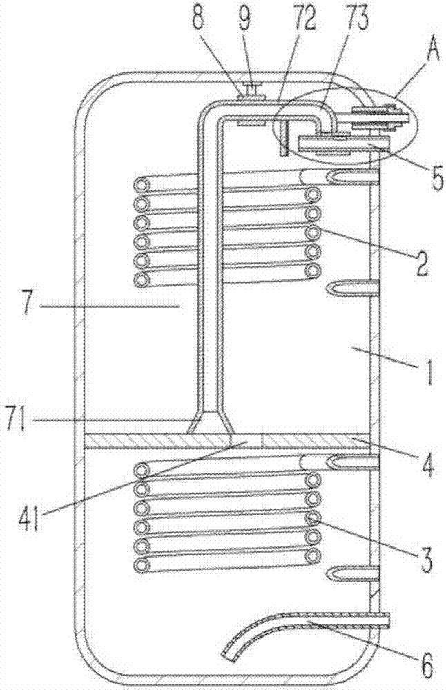
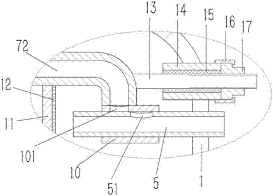
[0015] Example: see figure 1 , 2 As shown, a double-coil heat exchange tank includes an inner tank 1 of the heat exchange tank, an upper coil 2 and a lower coil 3 are respectively inserted at the upper and lower ends of the inner tank 1, and the upper coil 2 and the lower coil 3 are respectively inserted. The lower coils 3 are all fixed on the inner tank 1, the upper coil 2 and the lower coil 3 and the inner tank 1 are inserted with a horizontal partition 4, and the partition 4 is fixed on the inner wall of the inner tank 1, so The top and bottom ends of the liner 1 are distributed and fixed with water inlet pipe 5 and water outlet pipe 6, and the upper coil pipe 2 is inserted with a vertical diversion pipe 7, and the upper end of the diversion pipe 7 is bent to form a horizontal guide. Pipe 72, the guide tube 72 is inserted with a guide sleeve 8, the guide sleeve 8 is fixed on the positioning bracket 9, the positioning bracket 9 is fixed on the inner tank 1, and the end of t...


PUM


Abstract

The invention discloses a heat exchange water tank provided with double coiled pipes. The heat exchange water tank comprises an inner container of the heat exchange water tank, wherein an upper coiledpipe and a lower coiled pipe are inserted into the upper end and the lower end of the inner container respectively and are both fixed on the inner container; a horizontal partition board is insertedbetween the upper coiled pipe and the lower coiled pipe and in the inner container; the partition board is fixed on the inner wall of the inner container; a water inlet pipe and a water outlet pipe are inserted and fixed to the top end and the bottom end of the inner container respectively; a vertical flow guide pipe is inserted in the upper coiled pipe, the upper end of the flow guide pipe is bent to form a horizontal guide pipe, the guide pipe is sleeved with a guide sleeve, the guide sleeve is fixed on a positioning bracket which is fixed on the inner container, an elbow pipe is formed at the tail end of the guide pipe and fixed on the outer wall of a bypass sleeve, a diffluence hole communicated with the elbow pipe is formed in the bypass sleeve which is inserted to the water inlet pipe in a sleeving manner, and a water outlet hole opposite to the diffluence hole is formed in the water inlet pipe. With the adoption of the heat exchange water tank, rapid discharge of water heated bythe lower coiled pipe of the heat exchange water tank can be realized.

Description

Technical field: [0001] The invention relates to the technical field of water heaters, in particular to a double-coil heat exchange tank. Background technique: [0002] At present, the heat exchange tank is generally composed of a cylinder body and a heat exchange coil placed on the cylinder body. The cylinder body is fixedly connected with water inlet and outlet pipes so as to realize heat exchange between the heat exchange coil tube and the water flowing out of the cylinder body. The heat exchange coil is located between the water inlet pipe and the water outlet pipe. At present, some long cylindrical water storage cylinders are generally equipped with two heat exchange coils. The two heat exchange coils are respectively located at the upper and lower ends of the water storage cylinder. The upper heat exchange coil is generally connected to auxiliary heating equipment such as electric heating. , the lower heat exchange coil is generally connected to solar heating equipmen...

Claims


Application Information

Patent Timeline
IPC IPC(8): F28D1/047
CPCF28D1/0477
Inventor 杨勇
Owner DONGGUAN LIANZHOU INTPROP OPERATION MANAGEMENT CO LTD
Features
  • Generate Ideas
  • Intellectual Property
  • Life Sciences
  • Materials
  • Tech Scout
  • Unparalleled Data Quality
  • Higher Quality Content
  • 60% Fewer Hallucinations
Learn More