AI technical title is built by Patsnap AI team. It summarizes the technical point description of the patent document.
A technology of rail wear and detection instrument, applied in instruments, measuring devices, railway vehicle shape measuring instruments, etc., can solve the problems of low work efficiency, decreased measurement accuracy, large workload, etc., saving manpower, small influence of human factors, The effect of low work efficiency
Active Publication Date: 2019-09-24
EAST CHINA JIAOTONG UNIVERSITY
View PDF7 Cites 0 Cited by
Summary
Abstract
Description
Claims
Application Information
AI Technical Summary
This helps you quickly interpret patents by identifying the three key elements:
Problems solved by technology
Method used
Benefits of technology
Problems solved by technology
[0003] In the prior art, the steel rail is usually tested by purely mechanical caliper measurement method. The measuring instrument of pure mechanical caliper measurement method is configured according to different rail models. The measuring instrument is clamped to the bottom of the rail, and then the top and side pointers of the instrument are pressed down. Hold the surface of the rail and read the measurement data at this time. However, the measuring instrument of the pure mechanical caliper measurement method has high requirements on the ability of the workers, a large workload, low work efficiency, and is greatly affected by human factors. Long-term use will cause the caliper to wear out. , resulting in a decrease in measurement accuracy and the inability to continuously detect the degree of wear of the entire rail
Method used
Image
Click on the blue label to locate the original text in one second.
Reading with bidirectional positioning of images and text.
Examples
Embodiment Construction
[0021] In order to make the objectives, features and advantages of the present invention more comprehensible, the specific embodiments of the present invention will be described in detail below with reference to the accompanying drawings. Several embodiments of the invention are shown in the drawings. However, the present invention can be implemented in many different forms and is not limited to the embodiments described herein. On the contrary, the purpose of providing these embodiments is to make the disclosure of the present invention more thorough and comprehensive.
[0022] It should be noted that when an element is referred to as being "fixed to" another element, it can be directly on the other element or a central element may also exist. When an element is considered to be "connected" to another element, it can be directly connected to the other element or an intermediate element may be present at the same time. The terms "vertical", "horizontal", "left", "right", "upper...
PUM
Abstract
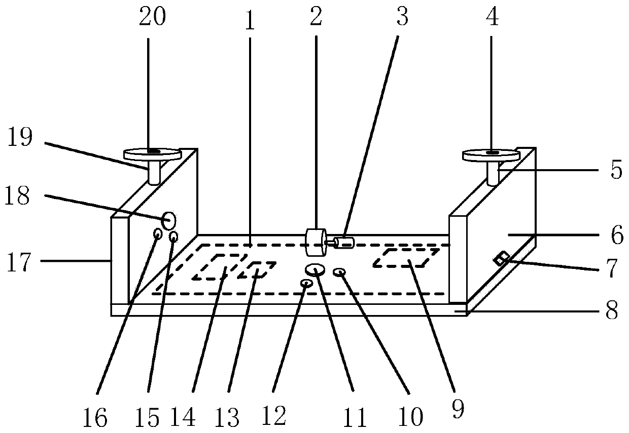
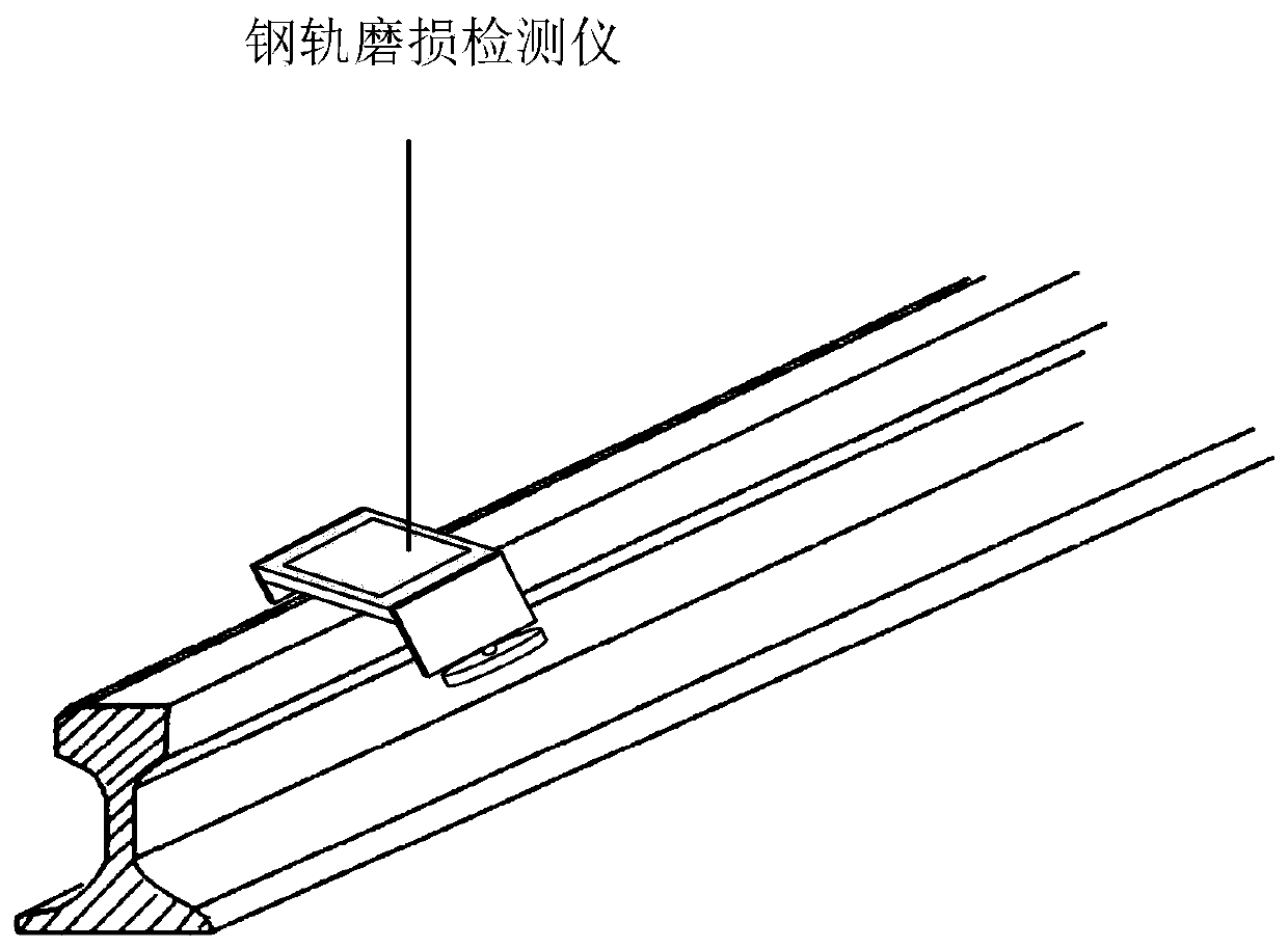
The invention discloses a rail wear detector, which is composed of a liquid crystal display screen, a driving wheel, a motor, an outer follower wheel, a second supporting pole, an outer metal baffle,a power switch, a top metal baffle, a battery, a second light source, a second camera, a second infrared range sensor, an SD card storage module, a main control board, a first light source, a first infrared range finder, an inner metal baffle, a first camera, a first supporting pole and an inner follower wheel. The rail wear detector is arranged on the rail to move along the rail, the rail head top surface and the rail head side surface of the rail are detected through the first camera, the first infrared range sensor, the second camera and the second infrared range sensor arranged on the railwear detector, the detected data and the detected images are compared with a standard rail, the rail wear degree is determined, and when the rail wear is detected to reach a severe injury degree, aninstrument actively reminds the user.
Description
Technical field [0001] The invention relates to a rail wear detection device, in particular to a rail wear detector. Background technique [0002] With the rapid development of railways, heavy-duty trains and high-speed trains have become more and more important in the railway transportation industry. The existence of heavy-duty trains and high-speed trains causes the rails to be worn and deformed. When the rails used on the line reach The severity of serious injuries will affect driving safety. According to the location, the rail wear can be divided into vertical wear on the top surface of the rail head and lateral wear on the side surface of the rail head. The rail wear should be tested regularly to ensure the safe running of the train. [0003] In the prior art, a purely mechanical caliper measurement method is usually used to detect rails. The purely mechanical caliper measurement method is configured according to different rail models. The measurement instrument is clamped to...
Claims
Application Information
Patent Timeline
Application Date:The date an application was filed.
Publication Date:The date a patent or application was officially published.
First Publication Date:The earliest publication date of a patent with the same application number.
Issue Date:Publication date of the patent grant document.
PCT Entry Date:The Entry date of PCT National Phase.
Estimated Expiry Date:The statutory expiry date of a patent right according to the Patent Law, and it is the longest term of protection that the patent right can achieve without the termination of the patent right due to other reasons(Term extension factor has been taken into account ).
Invalid Date:Actual expiry date is based on effective date or publication date of legal transaction data of invalid patent.

