Automatic transfer device and transfer method

A technology of a transfer device and a trigger device, which is applied in the directions of transportation and packaging, conveyor objects, etc., can solve the problems of inability to meet the needs of automated production and the low degree of automation of transfer equipment, and achieve the effect of reducing inertia and improving stability.

Inactive Publication Date: 2015-06-03
苏州久工自动化科技有限公司
View PDF7 Cites 14 Cited by
  • Summary
  • Abstract
  • Description
  • Claims
  • Application Information

AI Technical Summary

Problems solved by technology

[0004] For this reason, the technical problem to be solved by the present invention is that the existing transfer equipment has a low degree of automation and cannot meet the technical defects of automatic production requirements, thus proposing a transfer device with a high degree of automation

Method used


Image

  • Automatic transfer device and transfer method
  • Automatic transfer device and transfer method
  • Automatic transfer device and transfer method

Examples


Embodiment 1

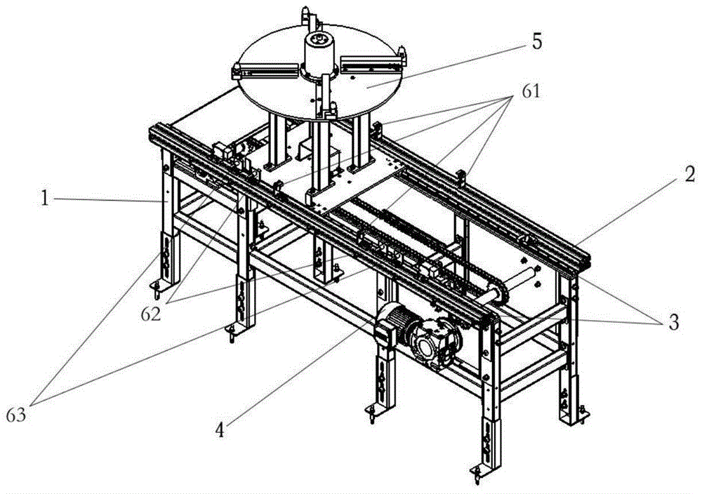
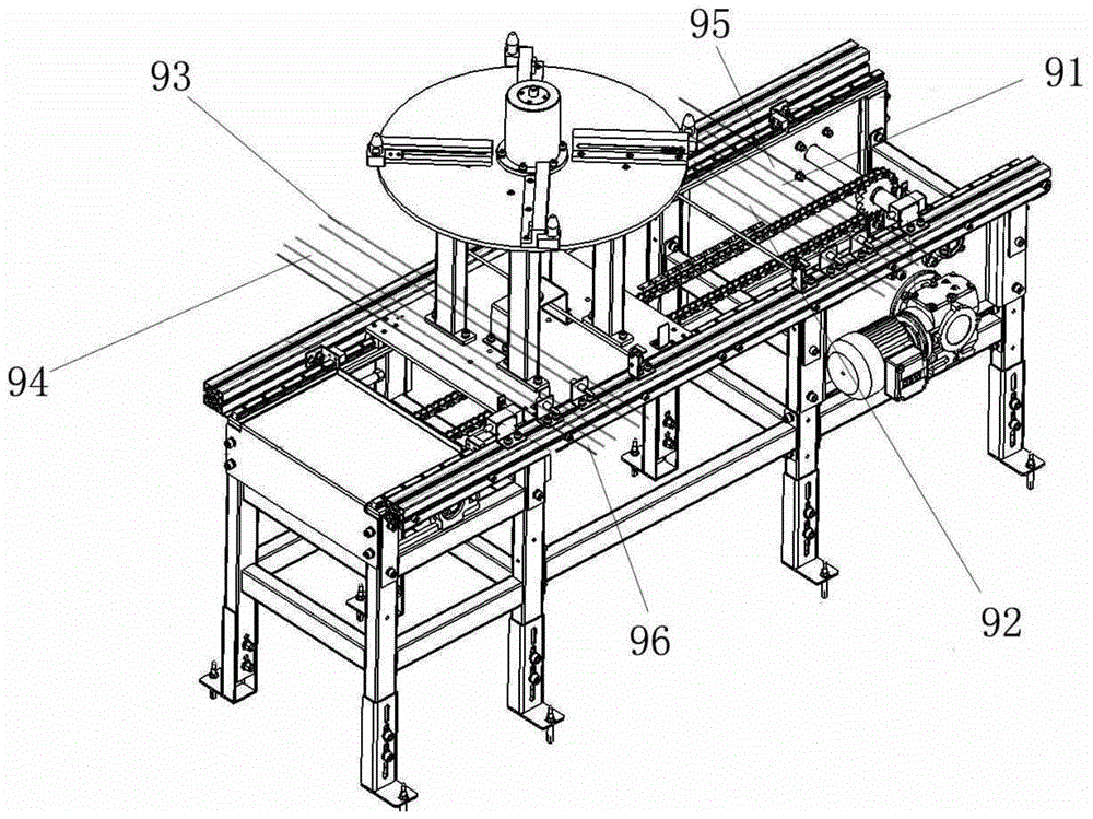
[0038] This embodiment provides an automatic transfer device, such as Figure 1-3 As shown, it includes: a support 1, which forms a transfer zone inside the support 1, a power assembly 4 (usually a motor) arranged on one side of the support 1, a beam 2 arranged at the top of the support 1, and arranged on the top of the support 1. The slide rail 3 on the inner side of the crossbeam 2 is driven by the transmission device of the power assembly 4. Driven by the transmission device, the moving assembly 5 moves back and forth in the transfer space along the slide rail 3. The length direction of the transfer section is The two sides are sequentially provided with a first stop position 95 and a second stop position 96, a first stop position 91 and a second stop position 94, a first deceleration position 92 and a second deceleration position 93 from outside to inside, as image 3 As shown; the transfer device of this embodiment is also provided with an automatic control device, which ...

Embodiment 2

[0053] This embodiment provides a transfer device, which is an improvement made on the basis of Embodiment 1. The difference from Embodiment 1 lies in the addition of safety equipment.

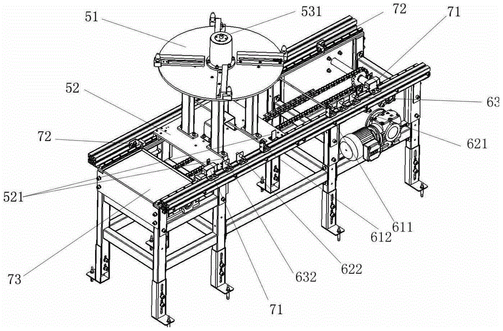
[0054]In the transfer device of this embodiment, the safety equipment includes safety limit switches 71 arranged at both ends of the beam 2 and located outside the transfer section, and a trigger piece 521 arranged on the sliding plate 52, the The trigger piece 521 is in contact with the safety limit switch 71 when the moving component 5 moves beyond the transfer zone, so as to forcibly turn off the power supply of the power component 4 .

[0055] Normally, the moving assembly 5 is controlled by the deceleration sensor 62 and the stop sensor 63 to move back and forth in the transfer zone, so as to realize the transportation of the workpiece. However, in some unexpected cases, the deceleration sensor 62 and the stop sensor 63 may fail, The moving assembly 5 may exceed the transfer interval, and...

Embodiment 3

[0060] This embodiment provides a transfer device, which is an improvement made on the basis of Embodiment 1 or 2. The difference from Embodiment 1 or 2 is that the loading tray 51 is provided with positioning blocks for fixing workpieces 515, such as Figure 5 shown. By arranging the positioning block 515, the workpiece can be fixed on the loading tray 51 to ensure that when the workpiece is running with the moving assembly 5, especially when the moving assembly 5 starts and stops, the workpiece will not be moved from the loading tray 51 by inertia. Falling down further improves the stability and safety of the overall transfer device.

[0061] In the transfer device of this embodiment, the loading tray 51 is provided with an adjustment device for adjusting the position of the positioning block 515, and the adjustment device includes an adjustment slot 513 formed on the side of the loading tray 51 along the radial direction. The rod 511 can move in the adjustment slot 513 an...


PUM


Abstract

The invention relates to an automatic transfer device. Existence sensors are set for sensing whether workpieces are arranged on a motion component or not so as to control operation time of a power component, speed reduction sensors are set for enabling the motion component to reduce speed before the stop position and reduce inertia of the motion component during stopping so as to improve operation stability of the transfer device and letting the motion component to stay in the accurate stopping position, and stop sensors are set for controlling the stopping time of the power component so as to enable the motion component to stop in the stop position. The existence sensors, the speed reduction sensors and the stop sensors realize automatic control motion process of circulating of workpieces from the feed position to the discharge position and to the feed position again. Furthermore, the invention provides an automatic transfer method of the automatic transfer device.

Description

technical field [0001] The invention relates to an automatic transfer device and a transfer method, belonging to the field of conveying equipment. Background technique [0002] The traditional power roller conveyor line realizes the product transportation through the friction between the product and the roller. During the whole conveying process, the motor needs to support the continuous rotation of each roller. The traditional power roller conveyor line consumes a lot of power, and the product and the roller will produce Friction, the roller will scratch the surface of the product, thus affecting the surface quality of the product. When the surface of the product is strict, it is not suitable to use the roller conveyor line to transport the product. [0003] Chinese patent document CN202625244U discloses a transmission device, which includes a fixed frame, a transmission surface, a propulsion device, an induction device, and a storage basket. The propulsion device contain...

Claims


Application Information

Patent Timeline
Patent Type & Authority Applications(China)
IPC IPC(8): B65G47/80
Inventor 张淑云罗恩·李·哈里森其他发明人请求不公开姓名
Owner 苏州久工自动化科技有限公司
Why Eureka
Try Eureka