Grid-side Power Factor Control Method of Dual-Stage Matrix Converter Based on Quasi-PR Control

A technology of power factor control and matrix converter, which is applied in the direction of AC power input conversion to AC power output, output power conversion device, high-efficiency power electronic conversion, etc. It can solve the problems of grid-side current phase shift and reduce system calculation Quantity, closed-loop control structure is simple, avoid the effect of rotating coordinate transformation

Inactive Publication Date: 2020-07-10
CHINA UNIV OF MINING & TECH
View PDF5 Cites 0 Cited by
  • Summary
  • Abstract
  • Description
  • Claims
  • Application Information

AI Technical Summary

Problems solved by technology

Regardless of which modulation strategy the rectifier stage adopts, the phase of its input current space vector comes from the phase of the grid-side voltage vector. In general, the phase of the grid-side voltage vector is directly used to replace the phase of the input-side current vector of the converter, so as to obtain the phase of the rectifier stage Switching duty cycle, but due to the existence of the input filter and changes in other system parameters, various reasons may cause the phase shift of the grid side current

Method used


Image

  • Grid-side Power Factor Control Method of Dual-Stage Matrix Converter Based on Quasi-PR Control
  • Grid-side Power Factor Control Method of Dual-Stage Matrix Converter Based on Quasi-PR Control
  • Grid-side Power Factor Control Method of Dual-Stage Matrix Converter Based on Quasi-PR Control

Examples


Embodiment Construction

[0022] Below in conjunction with accompanying drawing, the present invention will be further described:

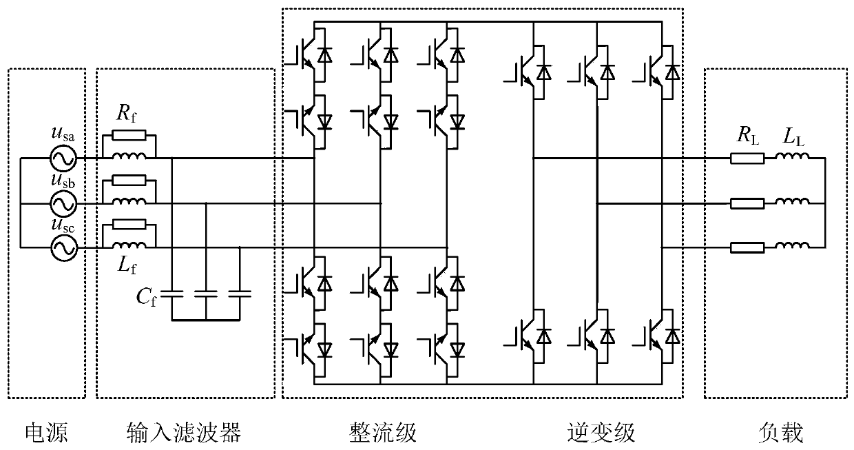
[0023] The two-stage matrix converter topology is as figure 1 As shown, the switching main circuit is divided into two stages: rectification stage and inverter stage. The rectification stage is a current source rectifier composed of six bidirectional switches, and the inverter stage is a traditional three-phase two-level voltage source inverter. Coupled together through the virtual DC side, so the rectifier stage can adopt zero-current commutation mode to reduce switching loss.

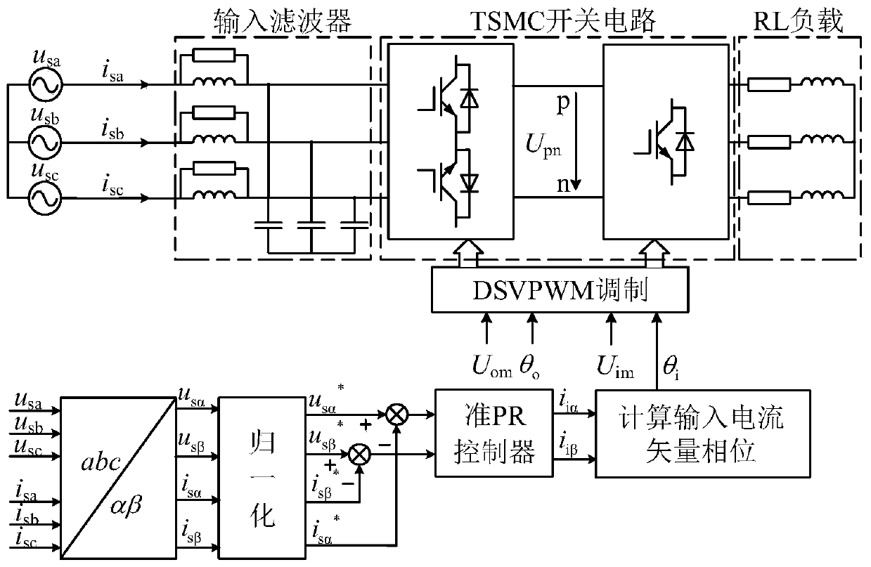
[0024] In order to solve the problem that the existing grid-side unit power factor control method needs to calculate the corresponding parameters off-line and has poor robustness, the present invention proposes the following figure 2 The grid-side power factor control method of the dual-stage matrix converter based on quasi-PR control is shown. Different from the existing grid-side power facto...


PUM


Abstract

The invention discloses a method for controlling the power factor of the grid side of a two-stage matrix converter based on quasi-PR control. The closed-loop voltage control method normalizes the grid-side voltage and current, uses the quasi-PR controller to realize the normalized value of the grid-side current to track the normalized value of the grid-side voltage, and determines the parameters of the quasi-PR controller based on root locus theoretical analysis , so as to ensure that the system has a large stability margin and steady-state accuracy. The output of the controller is used as the current modulation vector on the input side of the dual-stage matrix converter, so that the grid-side voltage and grid-side current are in phase. Beneficial effects of the present invention: the rotation coordinate transformation is avoided, the amount of calculation is reduced, and the same performance as that of the PI control can be obtained; when the system parameters change, the adaptive adjustment of the current vector at the input side can be realized, thereby realizing the unit power factor at the grid side , with better robustness.

Description

technical field [0001] The invention relates to a dual-stage matrix converter, in particular to a quasi-PR control-based dual-stage matrix converter grid-side power factor control method, which belongs to the field of dual-stage matrix converter control. Background technique [0002] The two-stage matrix converter (Two-Stage Matrix Converter, TSMC) is derived on the basis of the traditional matrix converter (Conventional Matrix Converter, CMC). The DC link in the middle of the traditional AC-DC-AC converter is omitted, so the power density of the converter is improved to a certain extent. In addition, TSMC also has many advantages such as bidirectional energy flow, sinusoidal input current, and controllable input power factor. It has great development potential in many fields such as motor drive, power quality improvement and wind power generation. [0003] Its topology is divided into a rectification stage and an inverter stage. The rectification stage is a current source...

Claims


Application Information

Patent Timeline
Patent Type & Authority Patents(China)
IPC IPC(8): H02M1/42H02M5/458
CPCH02M1/4216H02M5/4585H02M1/007Y02B70/10
Inventor 公铮孙宁张海军孙悦昕戴鹏王瀚哲
Owner CHINA UNIV OF MINING & TECH
Why Eureka
Try Eureka