A ball end milling cutter

A ball-end milling cutter and cutting tool technology, which is applied to milling cutters, milling machine equipment, metal processing equipment, etc., can solve the problems of unsatisfactory requirements, troublesome, difficult disassembly and assembly, etc.

Active Publication Date: 2019-06-07
TAIZHOU HONGXIANG POWER MACHINERY
View PDF1 Cites 0 Cited by
  • Summary
  • Abstract
  • Description
  • Claims
  • Application Information

AI Technical Summary

Problems solved by technology

[0003] In modern machining technology, milling cutters are widely used as the main workpiece of milling. For example, the utility model patent with the publication number CN 205967565U includes arbor, cutter teeth and blade body. Although the structure of the utility model patent is simple, However, due to its difficulty in disassembly and assembly, it is easy to cause unnecessary troubles in the processing process and cannot meet the needs of modern industry.

Method used


Image

  • A ball end milling cutter
  • A ball end milling cutter
  • A ball end milling cutter

Examples


Embodiment Construction

[0017] The following will clearly and completely describe the technical solutions in the embodiments of the present invention with reference to the accompanying drawings in the embodiments of the present invention. Obviously, the described embodiments are only some, not all, embodiments of the present invention. Based on the embodiments of the present invention, all other embodiments obtained by persons of ordinary skill in the art without making creative efforts belong to the protection scope of the present invention.

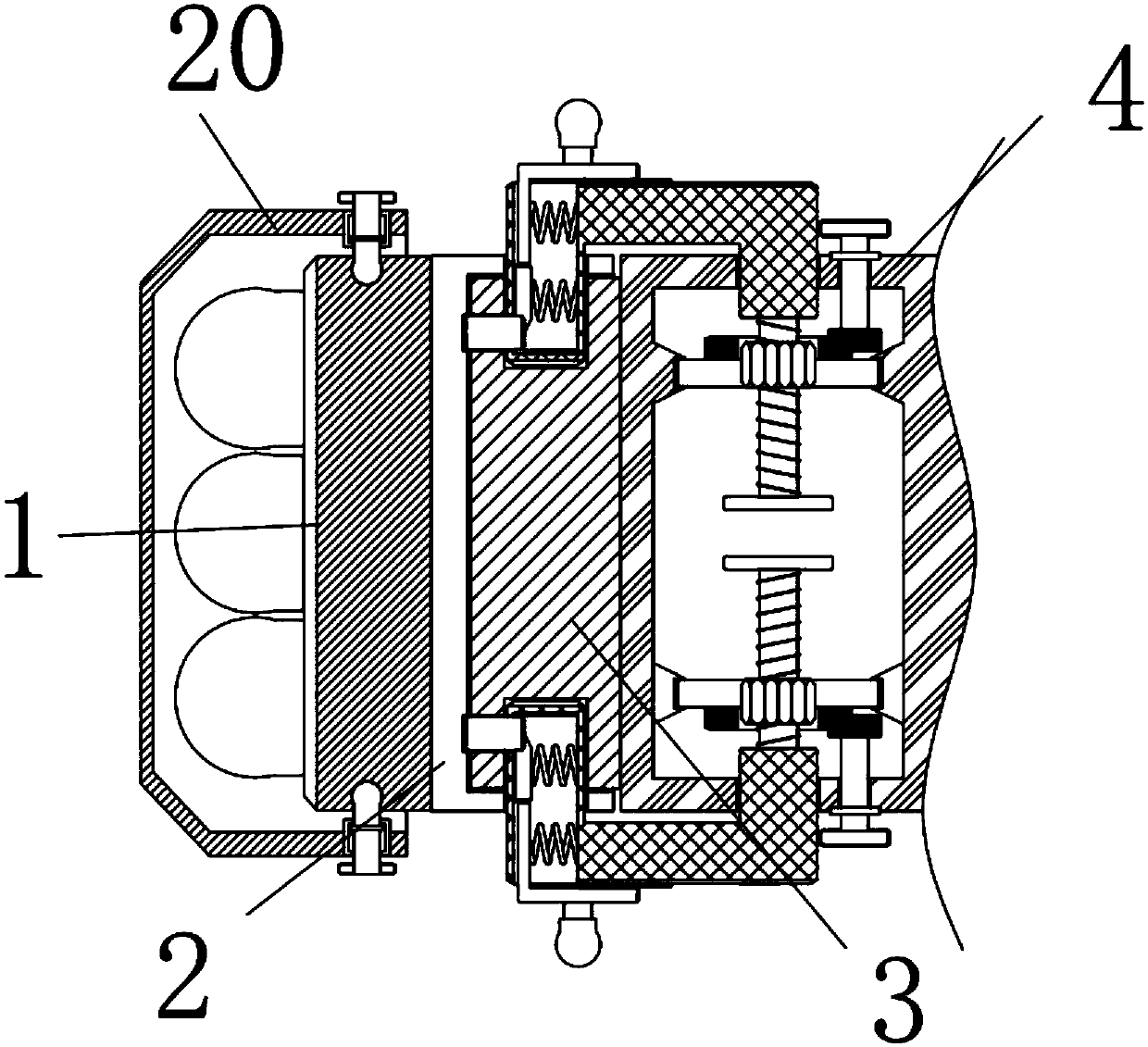
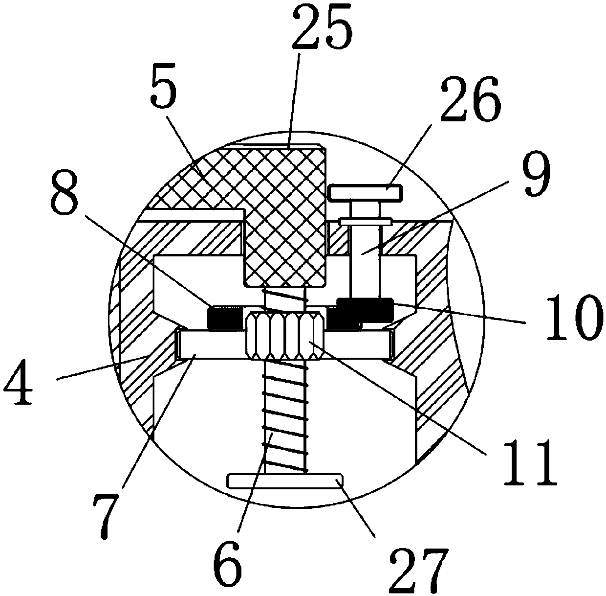
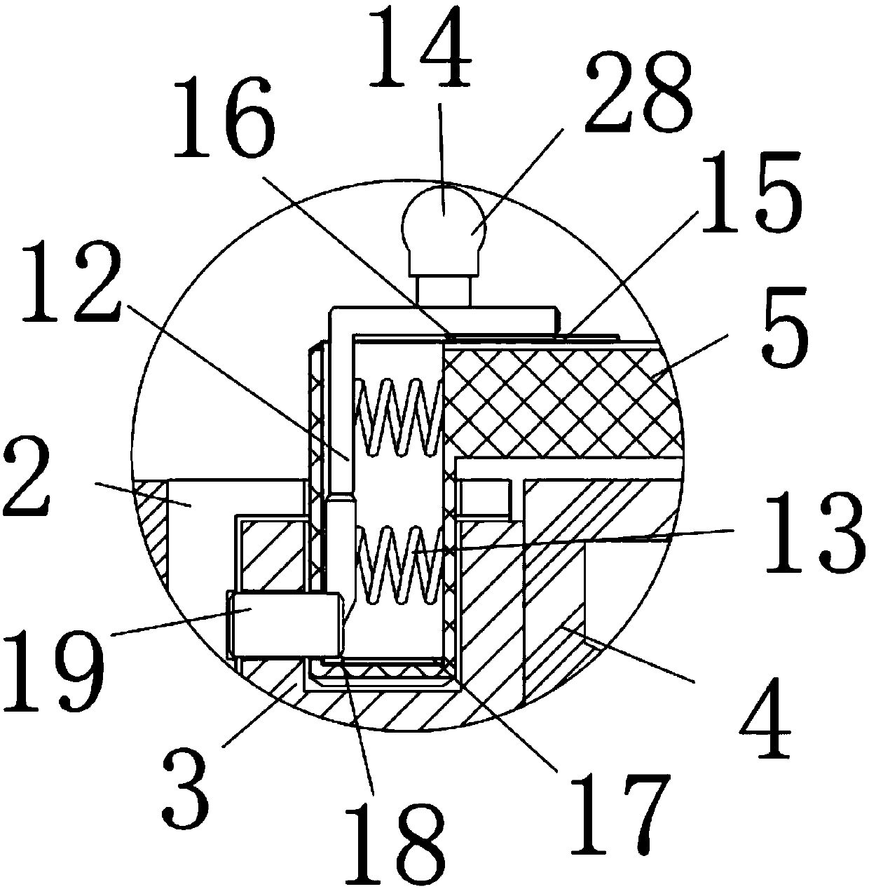
[0018] see Figure 1-4 , the present invention provides a technical solution: a ball end mill, including a cutter 1 and a slot 2, the outer wall of the right side of the cutter 1 is equipped with a slot 2, the cutter 1 can cut the workpiece, and the right side of the slot 2 An extension rod 4 is installed on the side, and an insert 3 is installed on the left outer wall of the extension rod 4, and the insertion block 3 penetrates the slot 2, so that the cutter ...


PUM


Abstract

The invention discloses a ball end milling cutter. The ball end milling cutter comprises a cutter body and a slot, wherein the slot is formed in the outer wall of the right side of the cutter body; aconnecting rod is arranged on the right side of the slot; an inserting block is arranged on the outer wall of the left side of the connecting rod and penetrates through the slot; clamping rods are arranged on the upper side and the lower side of the connecting rod; second sliding blocks are arranged on the outer walls of the bottom parts of first clamping blocks; and second slide ways are arrangedon the outer walls of the second sliding blocks and are connected to the inner walls of the clamping rods. The ball end milling cutter has the advantages that the purpose that the cutter body and a lathe are connected with each other can be achieved through the connecting rod, the purpose of enabling the clamping rods to be put up or put down can be achieved by twisting twist rods through the slot and the inserting block so that the cutter body can be rapidly mounted and dismounted, the purpose of fixing the cutter body and the connecting rod more stably can be achieved through the first clamping blocks, the purpose of enabling the first clamping blocks to be retracted can be achieved by pulling pull rods so that the clamping rods can smoothly lift and dismount the cutter body, and therefore the requirements of people can be met.

Description

technical field [0001] The invention relates to the technical field, in particular to a ball end milling cutter. Background technique [0002] Milling is a high-precision machining method that uses a rotating multi-blade tool to cut a workpiece. When working, the tool rotates (for the main movement), the workpiece moves (for the feed movement), and the workpiece can also be fixed, but at this time the rotating tool must also move (to complete the main movement and the feed movement at the same time). Machine tools for milling include horizontal milling machines or vertical milling machines, as well as large gantry milling machines. These machine tools can be ordinary machine tools or CNC machine tools. [0003] In modern machining technology, milling cutters are widely used as the main workpiece of milling. For example, the utility model patent with the publication number CN 205967565U includes arbor, cutter teeth and blade body. Although the structure of the utility model...

Claims


Application Information

Patent Timeline
Patent Type & Authority Patents(China)
IPC IPC(8): B23C5/10B23C5/26
CPCB23C5/1009B23C5/26
Inventor 梅锦初
Owner TAIZHOU HONGXIANG POWER MACHINERY
Why Eureka
Try Eureka