Friction hot melting device and method for PE pipes

A technology of friction heat and friction sheet, which is applied in the field of hot-melt welding of PE pipes, can solve the problems of large fluctuations in the temperature of the heating plate, affecting the control of the temperature of the heating plate, and the wide deviation range between the temperature of the heating plate and the requirements, so as to achieve saving Power consumption and the effect of improving welding efficiency

Active Publication Date: 2017-05-31
GUANGDONG INSPECTION & RES INST OF SPECIAL EQUIP ZHUHAI INSPECTION INST +2
View PDF8 Cites 4 Cited by
  • Summary
  • Abstract
  • Description
  • Claims
  • Application Information

AI Technical Summary

Problems solved by technology

The heating plate of some welding machines has the problem of temperature uniformity and display deviation that cannot meet the requirements of national standards. On the other hand, because the national standard does not clearly stipulate the temperature stability requirements and allowable operating temperature range of the heating plate, the heating plate of some The temperature fluctuation of the heating plate is relatively large, and the deviation range between the heating plate temperature set by the manufacturer and the requirement is wide, which directly affects the control of the heating plate temperature
In addition, during the whole process, the preheating of the heating plate takes a certain amount of time, which affects the efficiency of the project to a certain extent

Method used


Image

  • Friction hot melting device and method for PE pipes
  • Friction hot melting device and method for PE pipes
  • Friction hot melting device and method for PE pipes

Examples


Embodiment Construction

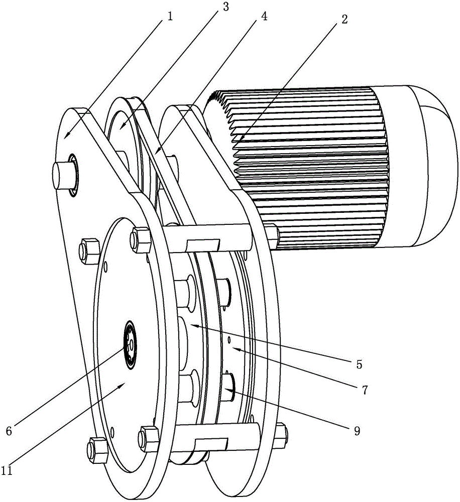
[0022] see figure 1 , a frictional hot-melt device for PE pipes of the present invention includes a bracket 1 and a drive motor 2 mounted on the bracket 1, the output shaft of the drive motor 2 is connected to a driving wheel 3, and the driving wheel 3 is connected by a belt 4 A driven wheel 5, a gear shaft 6 is installed at the center of the driven wheel 5, and a fixed disk 7 is engaged with both ends of the gear shaft 6.

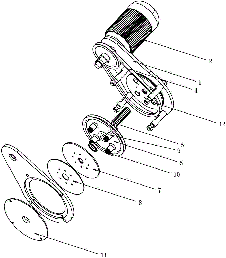
[0023] see further figure 2 , the outer side of the fixed disk 7 is fixed with a friction plate 8, and the fixed disk 7 and the friction plate 8 are fixed by rivets. At least two sleeves 9 are provided on both sides of the driven wheel 5. In this embodiment, the Both sides of the driven wheel 5 are provided with four sleeves 9, and the four sleeves 9 are evenly distributed on the upper, lower, left, and right sides of the driven wheel 5. The sleeve 9 is sleeved with a stage clip 10, and the stage clip 10 One end abuts against the driven wheel 5, a posi...


PUM


Abstract

The invention discloses a friction hot melting device for PE pipes. The friction hot melting device comprises a support and a driving motor installed on the support. An output shaft of the driving motor is connected with a driving wheel. A gear shaft is installed in the center of a driven wheel. The two ends of the gear shaft both are engaged with fixed disks. Friction pieces are fixedly installed on the outer sides of the fixed disks. Two or more sleeves are arranged on the two sides of the driven wheels. Compressed springs are sleeved with the sleeves. Two heat production disks are fixedly installed in the position, located on the outer sides of the two friction pieces, of racks correspondingly, and the friction pieces make close contact with the heat production disks. The friction pieces are driven through the driving motor to make friction with the heat production disks to produce heat. The invention further discloses a hot melting method for the PE pipes. The friction hot melting device is utilized to replace a heating plate; the heat production disks are introduced between the two PE pipes to be welded and make close contact with the two PE pipes to be welded; and by means of high-speed rotation of the driving motor, friction is conducted to produce the heat, the end faces of the PE pipes to be welded are subjected to hot melting and mutually connected, and friction heat input is same. The problems of the nonuniformity of temperature, the deviation of displaying, the fluctuation of the temperature and the like of the heating plate can be solved.

Description

technical field [0001] The invention relates to a hot-melt welding process for PE pipes, in particular to a frictional hot-melt device and method for PE pipes. Background technique [0002] Polyethylene (PE) pipes are widely used in urban gas pipeline projects because of their long service life, strong corrosion resistance, and excellent mechanical properties (bending properties). The quality of their welding is closely related to the safety of people's lives and property . [0003] The hot-melt welding machine widely used at present is a welding equipment specially used for connecting polyethylene (PE) pipes. It has the characteristics of low construction cost, simple operation and good welding quality. At present, the common hot-melt welding machine is mainly hydraulic control type, and its main components include connecting lines such as main engine, heating plate, milling cutter, frame, fixture, oil pipe and data transmission line. The main engine is used to control th...

Claims


Application Information

Patent Timeline
Patent Type & Authority Applications(China)
IPC IPC(8): B29C65/06B29K23/00B29L23/00
CPCB29C65/0681B29C66/1142B29C66/5221B29K2023/06B29L2023/00B29C66/0222B29C66/71B29C66/73921Y02A20/20
Inventor 陈英红杨剑赟丛成龙王磊戚政武矫庆泽汤景升庞慕妮张俊豪
Owner GUANGDONG INSPECTION & RES INST OF SPECIAL EQUIP ZHUHAI INSPECTION INST
Why Eureka
Try Eureka