Folding type seat

A folding seat technology, applied in vehicle seats, movable seats, detachable/non-detachable seats, etc., can solve problems such as poor structural strength, loud collision sound, and abnormal collision noise, and achieve strong load-bearing capacity , reduce the vertical height, reduce the effect of bearing pressure

Pending Publication Date: 2018-05-11
沃勒(天津)汽车制造有限公司
View PDF9 Cites 3 Cited by
  • Summary
  • Abstract
  • Description
  • Claims
  • Application Information

AI Technical Summary

Problems solved by technology

[0003] The existing folding seats on the market have a relatively complex structure, the overall weight of the seat is relatively large, and the quality and performance of the seat are not stable after long-term use. According to the different force modes when opening, they can be divided into two types: one is open The last is supported by the ground, and the other is supported by a lever cantilever structure seat; these two states have corresponding disadvantages. The first one, when it is opened to contact the ground, due to the heavy weight of the seat itself, coupled with the structure itself Due to the defect, it will be in a state of weightlessness for a short time, so that there will be abnormal collision noise when the support part is in contact with the ground. Because the seat is used in a closed environment in the car, the collision sound is loud, which is not easy for users to accept, and may cause Damage to other parts; the second type, due to the force of the cantilever structure, after the seat is opened, under normal use, the weight of the seat itself plus the weight of the occupant will all gather on the backrest and the seat. At the center of rotation, there is no external auxiliary force. This kind of structure has poor strength and is easily deformed and damaged during use. A folding seat is now provided

Method used


Image

  • Folding type seat
  • Folding type seat
  • Folding type seat

Examples


Embodiment Construction

[0039] The present invention will be described in further detail below in conjunction with the accompanying drawings, wherein the same components are denoted by the same reference numerals. It should be noted that the words "front", "rear", "left", "right", "upper" and "lower", "bottom" and "top" used in the following description refer to the Directions, the words "inner" and "outer" refer to directions toward or away from, respectively, the geometric center of a particular component.

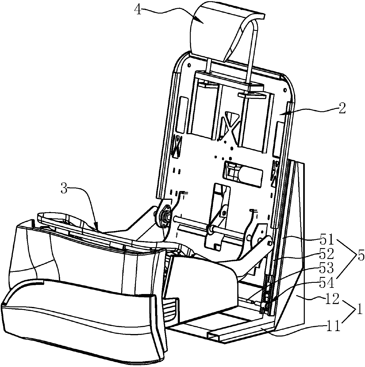
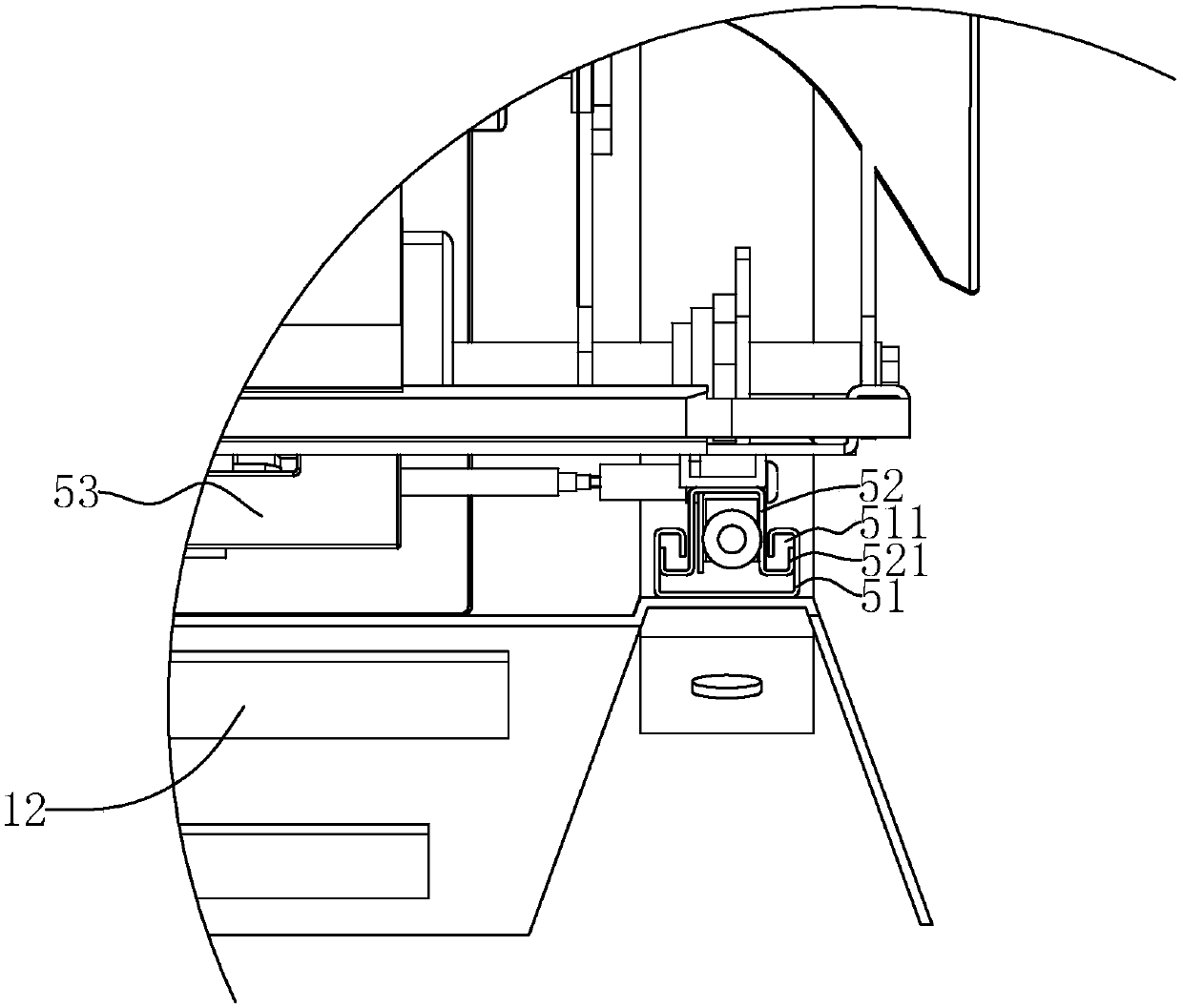
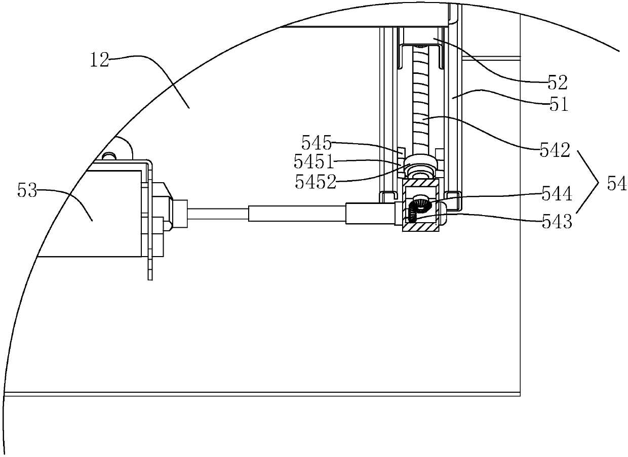
[0040] A folding seat such as figure 1 As shown, it includes a base 1, a back frame 2 slidably arranged on the base 1, a seat cushion frame 3 rotated on the lower side of the back frame 2, and a headrest fixing plate 4 arranged on the upper side of the back frame 2, wherein the seat The cushion frame 3 can rotate 90 degrees along the horizontal axis, so that the seat cushion is rotated to an open state for passengers to ride or a vertically folded state to reduce the space occupancy rate.

[00...


PUM


Abstract

The invention discloses a folding type seat. According to the key points of the technical scheme, the folding type seat comprises a base, a backrest skeleton arranged on the base and a seat cushion skeleton arranged on the lower side of a backrest hanging frame; the backrest skeleton is slidably arranged on the base, and a lifting device drives the backrest skeleton to slide up and down in the vertical direction; the backrest skeleton is provided with a rotating device which drives the seat cushion skeleton to rotate along a horizontal rotating shaft in the vertical direction; and a connectingrod mechanism is hinged to the lower side of the seat cushion skeleton, and when the seat cushion skeleton rotates to the horizontal state, the seat cushion skeleton is supported by the connecting rod mechanism. Through the connecting rod mechanism arranged on the lower surface of the seat cushion skeleton, when the seat cushion skeleton rotates to the horizontal state, the seat cushion skeletonis supported on the ground by the connecting rod mechanism, and meanwhile, during rotating, the seat cushion skeleton produces pulling force to the connecting rod mechanism, so that abnormal sound generated when the connecting rod mechanism makes contact with the ground is small.

Description

technical field [0001] The present invention relates to a seat, and more particularly, it relates to a folding seat. Background technique [0002] Folding seats are suitable for the automotive industry, mostly in commercial vehicles, and have the advantages of small storage space and electric folding. [0003] The existing folding seats on the market have a relatively complex structure, the overall weight of the seat is relatively large, and the quality and performance of the seat are not stable after long-term use. According to the different force modes when opening, they can be divided into two types: one is open The last is supported by the ground, and the other is supported by a lever cantilever structure seat; these two states have corresponding disadvantages. The first one, when it is opened to contact the ground, due to the heavy weight of the seat itself, coupled with the structure itself Due to the defect, it will be in a state of weightlessness for a short time, s...

Claims


Application Information

Patent Timeline
Patent Type & Authority Applications(China)
IPC IPC(8): B60N2/30B60N2/22B60N2/832
CPCB60N2/3027B60N2/3047B60N2002/2204
Inventor 高玉友
Owner 沃勒(天津)汽车制造有限公司
Why Eureka
Try Eureka