Crack grouting device with controllable grouting speed

A gap and speed technology, applied in the field of gap treatment equipment, can solve the problems of uneven amount of slurry sprayed, difficult to control grouting speed, poor gap filling effect, etc., and achieve good coverage effect.

Inactive Publication Date: 2018-05-11
HENAN ZHIYING ELECTRONICS TECH CO LTD
View PDF0 Cites 6 Cited by
  • Summary
  • Abstract
  • Description
  • Claims
  • Application Information

AI Technical Summary

Problems solved by technology

[0003] However, the existing gap grouting device has some shortcomings during use. The speed of grouting is difficult to control, so that in the process of filling the gap, the amount of grout ejected is not uniform, and the grout put into the gap , it is difficult to fit the gap completely, and if it cannot be processed in time, the filling effect of the gap will not be good.

Method used


Image

  • Crack grouting device with controllable grouting speed
  • Crack grouting device with controllable grouting speed

Examples


Embodiment Construction

[0018] The following will clearly and completely describe the technical solutions in the embodiments of the present invention with reference to the accompanying drawings in the embodiments of the present invention. Obviously, the described embodiments are only some, not all, embodiments of the present invention.

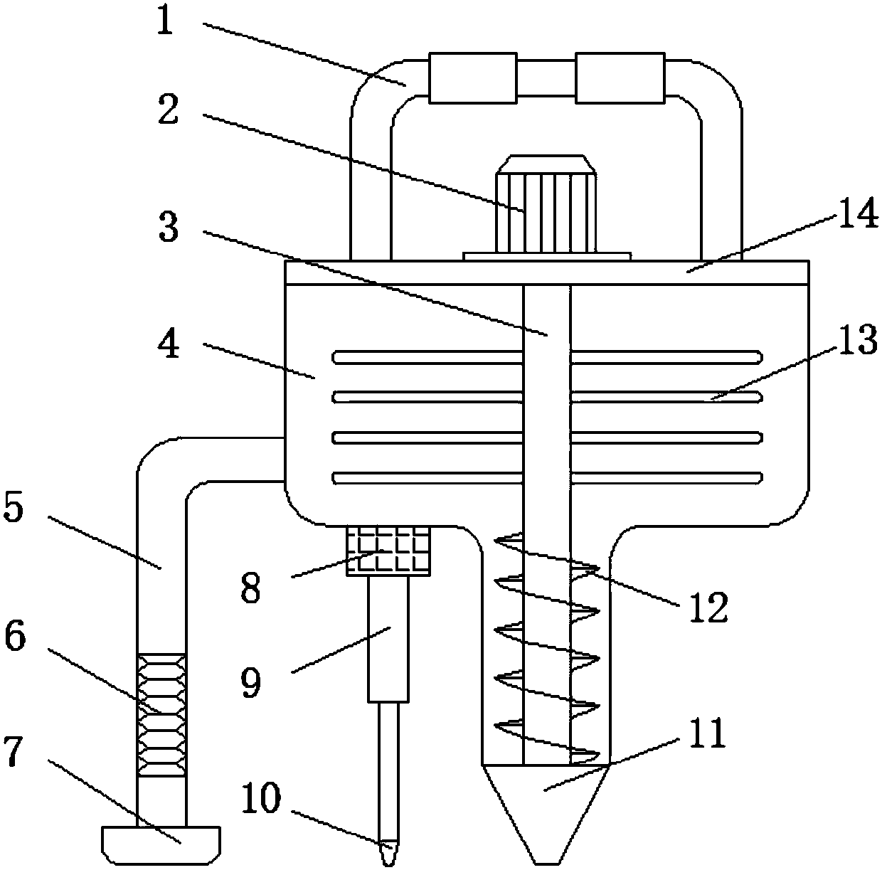
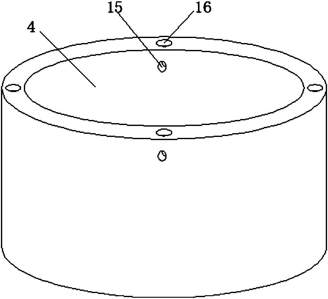
[0019] refer to Figure 1-2 , a gap grouting device with controllable grouting speed, including a grout storage bin 4 and a discharge head 11, the top of the grout storage bin 4 is connected to the snap-fit ​​welded on the cover plate 14 through the snap-fit ​​groove 16 opened, and the cover plate 14 The motor 2 is fixed by bolts at the middle position of the top, and the motor 2 is connected to the rotating shaft 3 inside the slurry storage bin 4 through a reducer. The rotating shaft 3 is welded with a stirring rod 13, which is located on the rotating shaft 3. The spiral blade 12 is welded below the bottom of the slurry storage bin 4, and the middle position of the ...


PUM


Abstract

The invention discloses a crack grouting device with the controllable grouting speed. The grouting device comprises a grout storage bin and a discharging head; the top of the grout storage bin is connected with a buckle welded to a cover plate through a clamping groove formed in the top of the grout storage bin; a motor is fixed to the middle of the top of the cover plate through a bolt and is intransmission connection with a rotating shaft located inside the grout storage bin through a speed reducer; stirring rods are welded to the rotating shaft; and a spiral blade is welded to the position, located below the stirring rods, of the rotating shaft. In the crack grouting device, the stirring rods and the spiral blade are arranged on the same rotating shaft inside the grout storage bin; andwhen conveyed, grout can be stirred through the stirring rods and meanwhile is conveyed through the spiral blade so that the grout can be stirred while conveyed uniformly, and the effect of the groutis better in use accordingly.

Description

technical field [0001] The invention relates to the technical field of gap treatment equipment, in particular to a gap grouting device with controllable grouting speed. Background technique [0002] Formation of cracks: During the hardening process of concrete, due to dehydration of concrete, shrinkage is caused, or cracks are caused by uneven expansion and contraction due to the influence of temperature difference. Concrete crack repair refers to the adoption of scientific methods to repair concrete cracks Technology. Concrete cracks generally have three states: static cracks, active cracks, and developing cracks. Conventional techniques for repairing concrete cracks generally have three methods: low-pressure glue injection repair, high-pressure repair and slotting repair. The selection of concrete crack treatment methods generally requires Factors to consider: Determining whether the crack is active or static. [0003] However, the existing gap grouting device has some s...

Claims


Application Information

Patent Timeline
IPC IPC(8): E04G23/02E01C23/09
CPCE04G23/0203E01C23/0966E01C23/098
Inventor 杨英虎
Owner HENAN ZHIYING ELECTRONICS TECH CO LTD
Why Eureka
Try Eureka