A self-propelled fertilization equipment driven by hydropower for farmland water utilization

A technology of farmland water conservancy and hydrodynamics, applied in fertilization devices, mechanical equipment, agriculture, etc., can solve the problems of fertilization, time-consuming, difficult farmland, etc.

Active Publication Date: 2020-04-17
蔡镇海
View PDF5 Cites 0 Cited by
  • Summary
  • Abstract
  • Description
  • Claims
  • Application Information

AI Technical Summary

Problems solved by technology

[0006] In order to overcome the disadvantages that it takes a lot of time to fertilize the farmland and it is difficult to uniformly fertilize the farmland, the technical problem to be solved by the present invention is to provide a method that does not need to consume a lot of time and can fertilize Fertilization equipment for uniform fertilization of farmland using hydrodynamic drive for self-propelled fertilization equipment

Method used


Image

  • A self-propelled fertilization equipment driven by hydropower for farmland water utilization
  • A self-propelled fertilization equipment driven by hydropower for farmland water utilization
  • A self-propelled fertilization equipment driven by hydropower for farmland water utilization

Examples


Embodiment 1

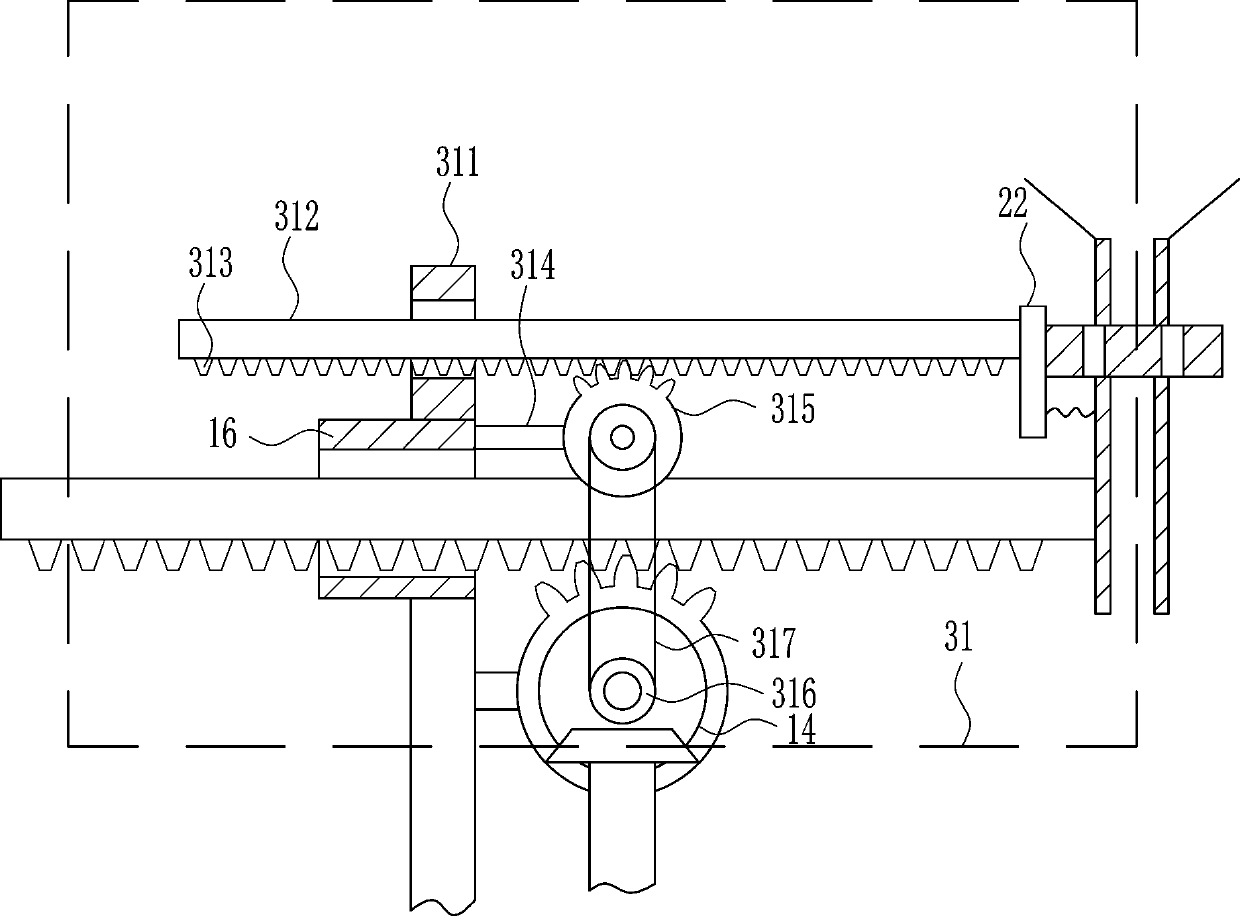
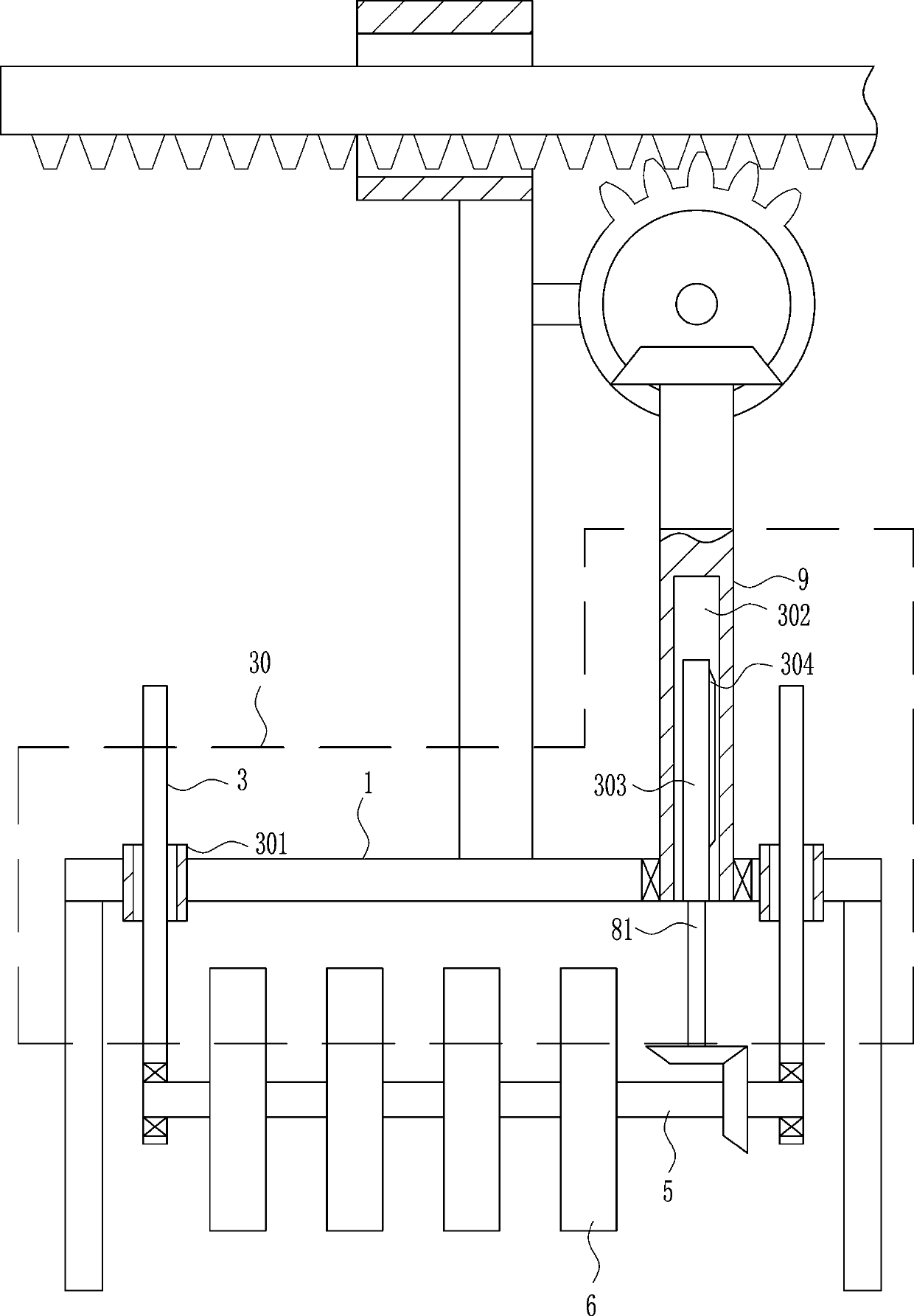
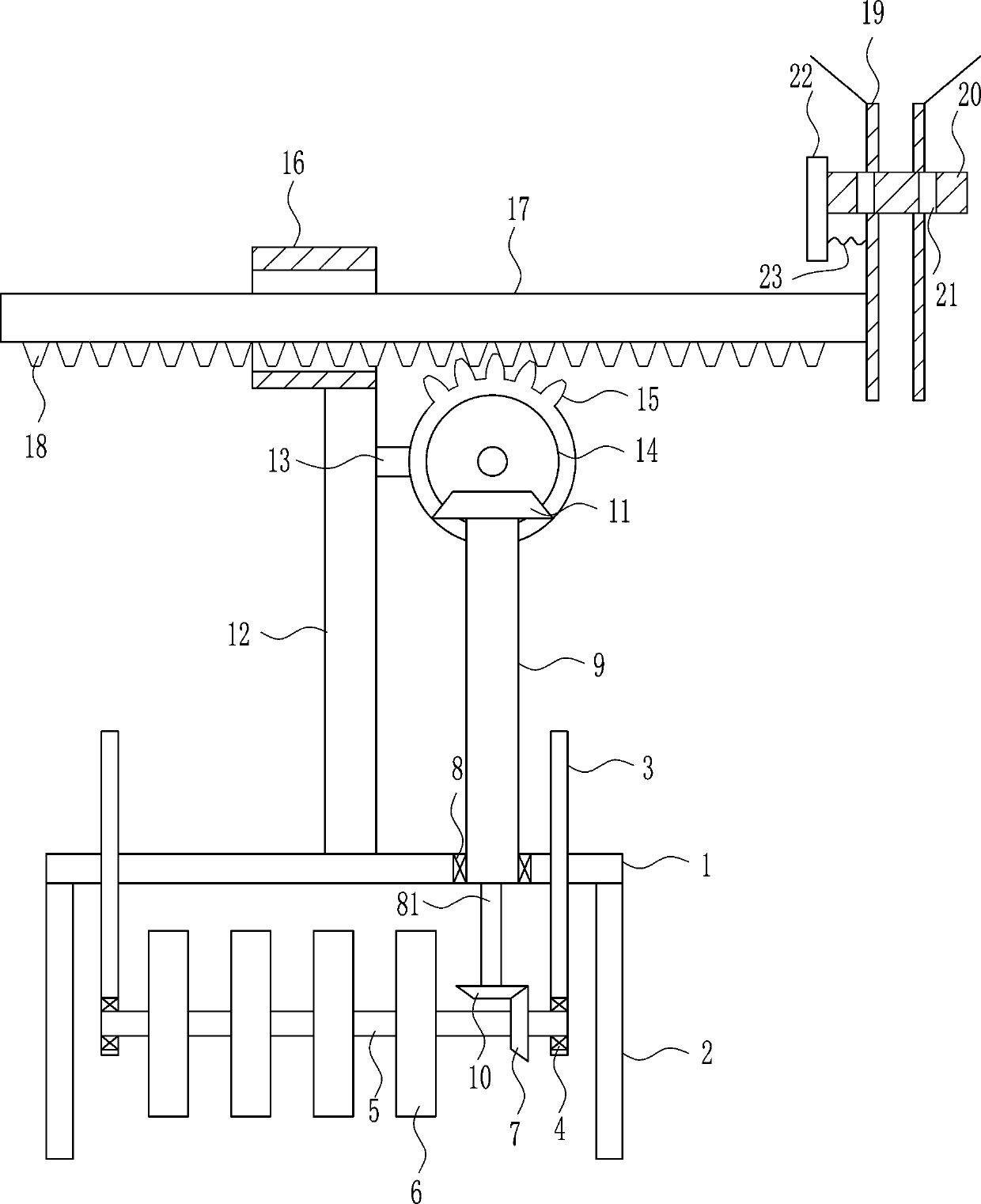
[0028] A self-propelled fertilization equipment driven by hydropower for farmland water, such as Figure 1-5 As shown, it includes a mounting plate 1, a bracket 2, a connecting rod 3, a first bearing seat 4, a first rotating rod 5, a rotating piece 6, a first bevel gear 7, a second bearing seat 8, and a second rotating rod 81 , the third rotating rod 9, the second bevel gear 10, the third bevel gear 11, the support plate 12, the first connecting block 13, the fourth bevel gear 14, the first sector gear 15, the first guide sleeve 16, The first guide rail 17, the first rack 18, the funnel 19, the block 20, the push plate 22 and the spring 23, the left and right sides of the lower side of the mounting plate 1 are installed with brackets 2 by welding, the left and right sides of the front side of the mounting plate 1 A connecting rod 3 is connected, and a first bearing seat 4 is installed on the inner lower side of the connecting rod 3 through bolt connection. The first bearing se...

Embodiment 2

[0030] A self-propelled fertilization equipment driven by hydropower for farmland water, such as Figure 1-5 As shown, it includes a mounting plate 1, a bracket 2, a connecting rod 3, a first bearing seat 4, a first rotating rod 5, a rotating piece 6, a first bevel gear 7, a second bearing seat 8, and a second rotating rod 81 , the third rotating rod 9, the second bevel gear 10, the third bevel gear 11, the support plate 12, the first connecting block 13, the fourth bevel gear 14, the first sector gear 15, the first guide sleeve 16, The first guide rail 17, the first rack 18, the funnel 19, the block 20, the push plate 22 and the spring 23, the left and right sides of the lower side of the mounting plate 1 are installed with brackets 2 by welding, the left and right sides of the front side of the mounting plate 1 A connecting rod 3 is connected, and a first bearing seat 4 is installed on the inner lower side of the connecting rod 3 through bolt connection. The first bearing se...

Embodiment 3

[0033] A self-propelled fertilization equipment driven by hydropower for farmland water, such as Figure 1-5 As shown, it includes a mounting plate 1, a bracket 2, a connecting rod 3, a first bearing seat 4, a first rotating rod 5, a rotating piece 6, a first bevel gear 7, a second bearing seat 8, and a second rotating rod 81 , the third rotating rod 9, the second bevel gear 10, the third bevel gear 11, the support plate 12, the first connecting block 13, the fourth bevel gear 14, the first sector gear 15, the first guide sleeve 16, The first guide rail 17, the first rack 18, the funnel 19, the block 20, the push plate 22 and the spring 23, the left and right sides of the lower side of the mounting plate 1 are installed with brackets 2 by welding, the left and right sides of the front side of the mounting plate 1 A connecting rod 3 is connected, and a first bearing seat 4 is installed on the inner lower side of the connecting rod 3 through bolt connection. The first bearing se...


PUM


Abstract

The invention relates to equipment for irrigation and water conservancy, in particular to self-travelling fertilizing equipment driven by water power for irrigation and water conservancy. In order toresolve the technical problem, the invention provides the self-travelling fertilizing equipment driven by water power for irrigation and water conservancy which does not require much time and is capable of uniformly fertilizing the farmland. The self-travelling fertilizing equipment driven by water power for irrigation and water conservancy comprises an installation board, supports, connecting rods, first bearing seats, a first rotating rod and the like. Left and right sides of the lower side of the installation board are equipped with the supports through a welding mode. With the self-travelling fertilizing equipment, there is no need to take much time. The farmland can be uniformly fertilized. A first guide rail and funnels are driven by water conservancy power to move leftwards and rightwards. Additionally, a baffle board is driven by water conservancy power to move leftwards and rightwards. Therefore, uniform left-right movement is achieved so that fertilizers are uniformly applied. During a fertilizing process, energy is saved. Water power of a water-conservancy ditch can be fully used.

Description

technical field [0001] The invention relates to water conservancy and farmland equipment, in particular to a self-propelled fertilization equipment driven by hydropower for farmland water. Background technique [0002] The benefits of water conservancy projects are random, and the benefits are different according to the different hydrological conditions every year. Farmland water conservancy projects are also closely related to changes in meteorological conditions. Wide range of influence. Water conservancy channels are water delivery structures, mostly used for irrigation and water diversion projects. When encountering a high mountain blocking the road, you can go around the mountain or dig a water tunnel to pass through it (see hydraulic tunnel); if it intersects with a river or ditch, you need to set up an aqueduct or an inverted siphon. In addition, there are buildings intersecting with bridges and culverts. things. [0003] At present, when fertilizing agriculture, m...

Claims


Application Information

Patent Timeline
Patent Type & Authority Patents(China)
IPC IPC(8): F16H37/12A01C15/00A01C19/00
CPCA01C15/008A01C19/00F16H37/124
Inventor 段伟华
Owner 蔡镇海
Why Eureka
Try Eureka