Hand-cranking driving type hand drill

A manual drilling and driving technology, used in portable drilling rigs, drilling/drilling equipment, metal processing equipment, etc., can solve the problems of limited drilling capacity, easy fatigue, not easy to carry, etc. The effect of promotion and application, simple structure

Inactive Publication Date: 2016-10-26
刘同珍
View PDF11 Cites 2 Cited by
  • Summary
  • Abstract
  • Description
  • Claims
  • Application Information

AI Technical Summary

Problems solved by technology

The common defect of the two is: firstly, the drilling ability of the two is limited: the former is driven by the grip strength of the hand, and the grip strength of people is very limited and prone to fatigue; The friction force between them is limited and easy to relax; secondly, when the two are drilling, the rotary motion of the drill rod and the axial feed motion are not synchronized, so it is difficult to improve the drilling efficiency
[0004] Chinese patent (authorized notification number CN204194874U) discloses a method of using metal wire to drive the gear to rotate, and then the gear pair rotates to drive the speed change wheel, the speed change wheel drives the flywheel, and the flywheel drives the drill body to rotate. Although this technical solution can realize the drilling function, There are many transmission parts, the quality of the flywheel is relatively heavy, and it is not easy to carry, and the winding problem of the metal wire driving the gear rotation is not easy to solve, and when drilling, the rotary motion of the drill rod is not synchronized with the axial feed motion, which cannot improve the drilling speed. Pore ​​efficiency
[0005] In order to synchronize the rotation and axial feed of the manual drill and improve drilling efficiency, the current technical solutions cannot meet the requirements

Method used


Image

  • Hand-cranking driving type hand drill
  • Hand-cranking driving type hand drill
  • Hand-cranking driving type hand drill

Examples


Embodiment Construction

[0019] In order to illustrate the structure and principle of the present invention more clearly, the hand-driven manual drill of the present invention will be further described in detail below in conjunction with the accompanying drawings.

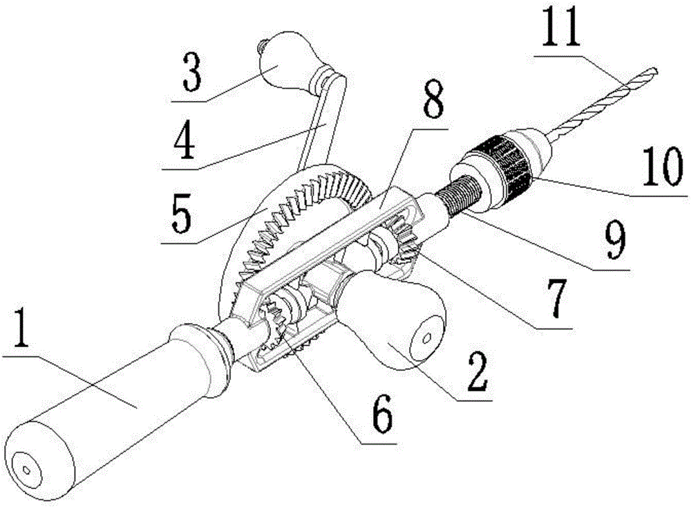
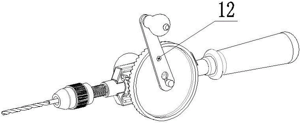
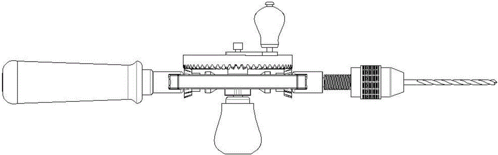
[0020] Such as figure 1 , figure 2 , image 3 , Figure 4 and Figure 5 As shown, a hand-driven manual drill consists of a main handle 1, an auxiliary handle 2, a hand handle 3, a rocker 4, a driving wheel 5, a driven wheel 6, a feed wheel 7, a support frame 8, and a driving shaft 9 , three-claw clamp 10, drill bit 11 and screw 12; the main handle 1 is fixed on the support frame 8, the auxiliary handle 2 is fixed on the connection seat 801 of the support frame 8, and the driving wheel 5 is installed on the connection of the support frame 8 On the shaft 802, a rocking bar 4 is installed between the connecting shaft of the support frame 8 and the driving wheel 5, and a hand crank 3 is installed at one end of the rocking bar 4, and the r...


PUM


Abstract

The invention relates to a hand-cranking driving type hand drill. The hand-cranking driving type hand drill consists of a main handle, an auxiliary handle, a crank handle, a rocker, a driving wheel, a driven wheel, a feed wheel, a support frame, a driving shaft, a three-claw clamp, a bit and a screw, wherein the main handle is fixed on the support frame; the auxiliary handle is fixed on a connecting seat of the support frame; the driving wheel is mounted on a connecting shaft of the support frame, and the rocker is mounted between the connecting shaft of the support frame and the driving wheel; the crank handle is mounted at one end of the rocker, and the rocker and the driving wheel are connected through the screw; the driven wheel and the feed wheel are mounted on the support frame, one side of the feed wheel and the driving shaft are connected and rotate simultaneously; the support frame and the driving shaft are in threaded connection; the three-claw clamp is mounted at the other end of the driving shaft; and the bit is arranged in the three-claw clamp. According to the hand-cranking driving type hand drill disclosed by the invention, rotating, drilling and axial feeding can be realized at the same time, so that the drilling efficiency is improved. Human labor can be fully used, holes which are difficult to drill can be drilled by using the hand-cranking driving type hand drill, and the hand-cranking driving type hand drill is simple in structure and can be widely popularized and applied.

Description

technical field [0001] The invention relates to a drilling tool, in particular to a hand driven manual drill. Background technique [0002] Among the current drilling equipment, the electric drill is easy to use, saves time and effort, but its price is relatively high, and it cannot work normally in the suburbs or without power supply. Therefore, the manual drill still has a greater role and market. [0003] Among the current public manual drilling technical solutions, the Chinese patent (authorized announcement number CN2284662Y) and the Chinese patent (authorized announcement number CN201333734Y) both disclose manual drills, both of which convert linear motion into rotary motion of the manual drill bit to achieve Drilling function. Among them, the former relies on the driving handle to drive the slider connected with the driving handle in a straight line, and then drives the drill rod to rotate through the action of the return spring and the return spring to realize drill...

Claims


Application Information

Patent Timeline
Patent Type & Authority Applications(China)
IPC IPC(8): B23B45/06
CPCB23B45/06
Inventor 刘同珍
Owner 刘同珍
Why Eureka
Try Eureka