
Novel explosion-proof valve

An explosion-proof valve, a new type of technology, applied in the direction of safety valve, balance valve, valve device, etc., can solve the problems of high process requirements, high opening pressure, small risk factor, etc., and achieve the effect of good explosion-proof performance and good sealing performance.

Inactive Publication Date: 2018-05-11
大禹阀门制造(天津)有限公司
View PDF0 Cites 0 Cited by
  • Summary
  • Abstract
  • Description
  • Claims
  • Application Information

AI Technical Summary

Problems solved by technology

[0002] At present, the common explosion-proof valves on the market are mainly divided into three categories: (1) Aluminum diaphragm type. The operating temperature of this type of explosion-proof valve is limited by the temperature of the aluminum diaphragm. Once the limit temperature is exceeded, the aluminum diaphragm will be heated (2) High-pressure explosion-proof valves, which use spring contraction to open and reset, the opening pressure is too high, not suitable for low-pressure furnaces, and the process requirements are high; (3) Gravity type, blasting The pressure is the self-gravity of the valve cover. Due to the limitation of the valve's own structure, the insulation layer is thin and not suitable for high temperature, and it is only pressed by gravity, which is prone to leakage and poor sealing.
[0003] For hot blast stoves, rotary kilns, incinerators and some flue gas pipelines that require higher temperatures, the temperature of the flue gas generated and transported is often above 800 ° C, and a large amount of steam or gas may be generated during the transport process. Waves, unstable gas pouring into the pipeline will cause dangerous situations such as pipeline burst due to excessive pressure, which will affect the normal operation of the equipment. Therefore, an explosion-proof valve with high temperature resistance, good sealing performance and low risk factor is required.

Method used


Image

  • Novel explosion-proof valve

Examples


Embodiment Construction

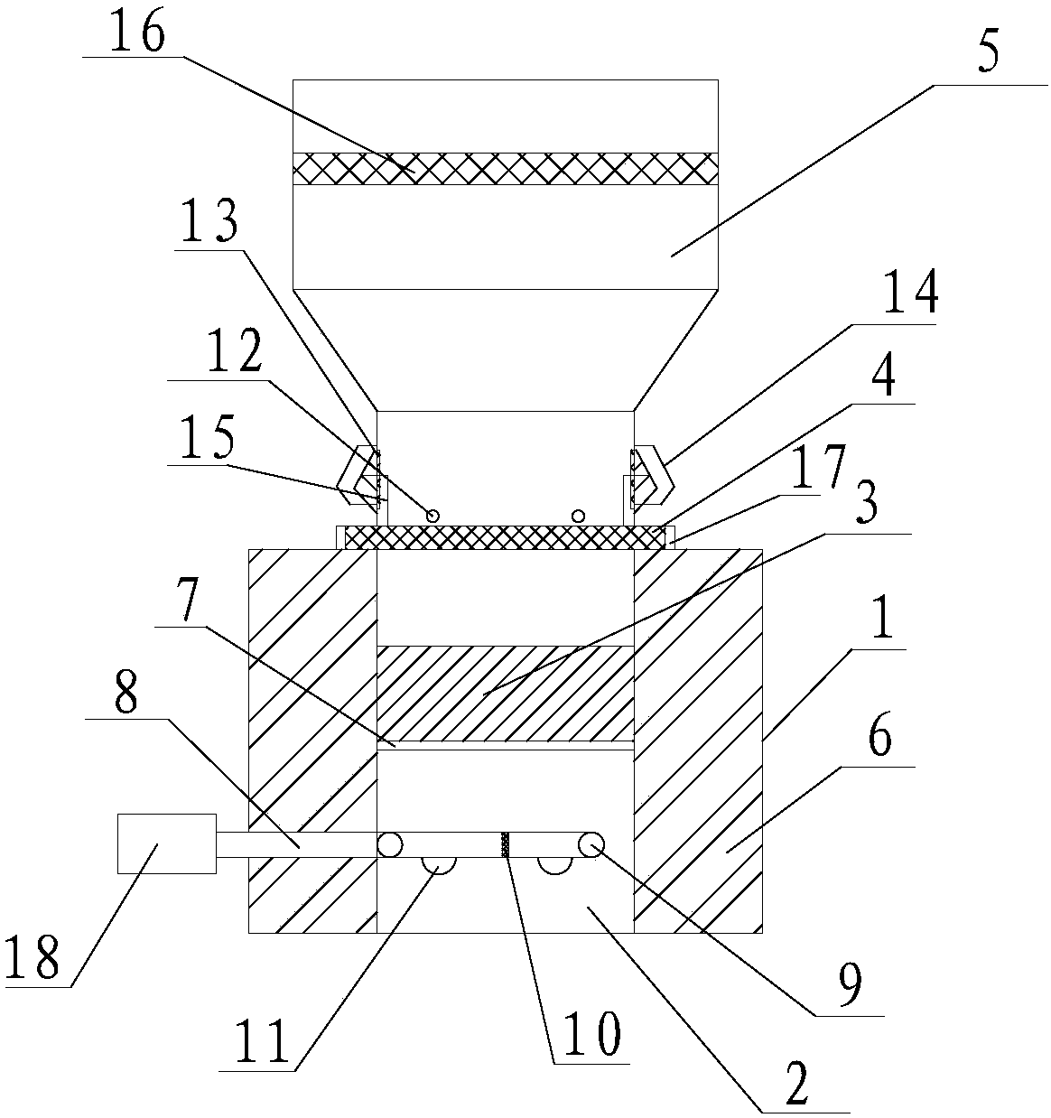
[0020] The present invention will be described in detail below in conjunction with the accompanying drawings.

[0021] Such as figure 1 As shown, a new explosion-proof valve of the present invention includes a valve body 1, and the valve body 1 includes an air intake pipe 2, an insulating layer I3, an insulating layer II4, and a buffer section 5. The outer side of the air intake pipe 2 is provided with Insulation layer 6, the heat insulation layer I3 is arranged in the middle of the intake pipe 2, the lower end of the heat insulation layer I3 is provided with a bracket 7, the two ends of the bracket 7 are fixed with the intake pipe 2, the heat insulation Layer II4 is arranged at the junction of the intake pipe 2 and the buffer section 5, the intake pipe 2 is provided with a guide tube 8, the guide tube 8 is provided with a rotating shaft 9, and the rotating shaft 9 is fixed on the intake pipe 2 On the inner wall, a hinge 10 is provided in the middle of the guide tube 8, a pre...


PUM


Abstract

The invention provides a novel explosion-proof valve. An insulating layer is arranged on the outer side of a gas inlet pipe; a heat insulation layer I is arranged at the middle part of the gas inlet pipe; the lower end of the heat insulation layer I is provided with a bracket; a heat insulation layer II is arranged at the connection part of the gas inlet pipe and a buffer section; the gas inlet pipe is provided with a diversion pipe; a rotary shaft is fixed on the inner wall of the gas inlet pipe; a hinge is arranged at the middle part of the diversion pipe; the lower end of the diversion pipeis provided with a pressure sensor I; the upper end of the heat insulation layer II is provided with a pressure sensor II; an explosion-proof door is installed at an exhaust hole; and the external ofthe heat insulation layer II is connected with an aluminum diaphragm. The novel explosion-proof valve has the beneficial effects that compressed air is poured into the diversion pipe, the diversion pipe forms a conical air curtain which is downward at 45 degrees, and high-temperature flue gas is prevented from overflowing; after each pressure sensor determines a pressure value which exceeds a preset pressure value, an explosion-proof door of the valve is opened to discharge the gas, and the internal pressure of a pipeline is relieved; and by utilizing the aluminum diaphragm as a bursting disc, the heat insulation layers block the high-temperature flue gas from thermally eroding the aluminum diaphragm, and the problem that the aluminum diaphragm is molten at high temperature is solved.

Description

technical field [0001] The invention belongs to the technical field of valves, in particular to a novel explosion-proof valve. Background technique [0002] At present, the common explosion-proof valves on the market are mainly divided into three categories: (1) Aluminum diaphragm type. The operating temperature of this type of explosion-proof valve is limited by the temperature of the aluminum diaphragm. Once the limit temperature is exceeded, the aluminum diaphragm will be heated (2) High-pressure explosion-proof valves, which use spring contraction to open and reset, the opening pressure is too high, not suitable for low-pressure furnaces, and the process requirements are high; (3) Gravity type, blasting The pressure is the gravity of the valve cover itself. Due to the limitation of the valve's own structure, the insulation layer is thin, which is not suitable for high temperature, and it is only pressed by gravity, which is prone to leakage and poor sealing. [0003] Fo...

Claims


Application Information

Patent Timeline
IPC IPC(8): F16K17/14
CPCF16K17/14
Inventor 孟令发
Owner 大禹阀门制造(天津)有限公司
Features
  • Generate Ideas
  • Intellectual Property
  • Life Sciences
  • Materials
  • Tech Scout
  • Unparalleled Data Quality
  • Higher Quality Content
  • 60% Fewer Hallucinations
Learn More