Escape path marking for aircraft

A technology of escape route and aircraft, which is applied in the field of escape route marking, can solve problems such as not being able to give soft colors, and achieve the effect of improving design feasibility

Pending Publication Date: 2018-05-11
LUFTHANSA TECH AG
View PDF8 Cites 1 Cited by
  • Summary
  • Abstract
  • Description
  • Claims
  • Application Information

AI Technical Summary

Problems solved by technology

[0008] The described use of perforated films has the disadvantage that only relatively bright colorings can be achieved, but in particular pastel colors cannot be given

Method used


Image

  • Escape path marking for aircraft
  • Escape path marking for aircraft
  • Escape path marking for aircraft

Examples


Embodiment Construction

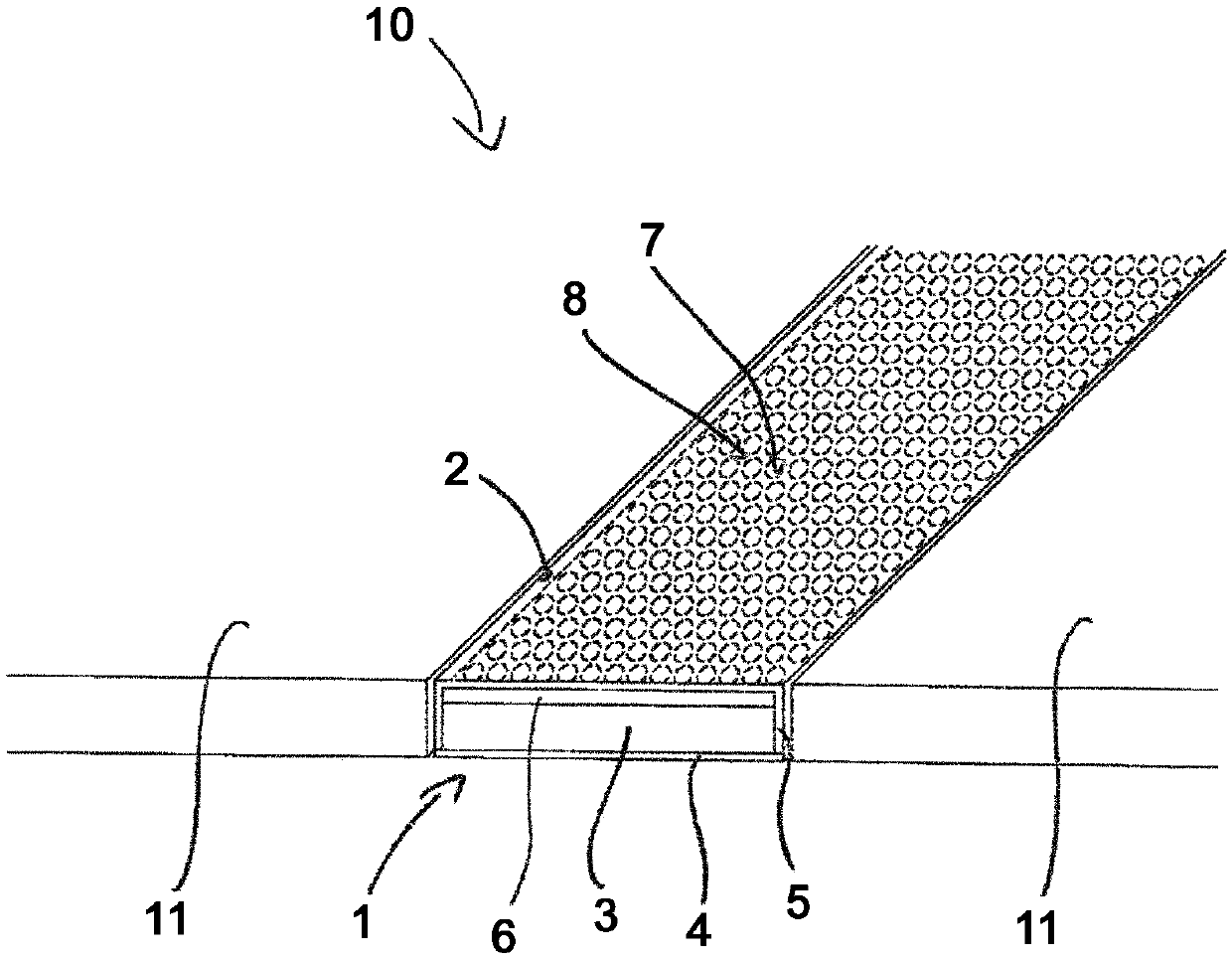
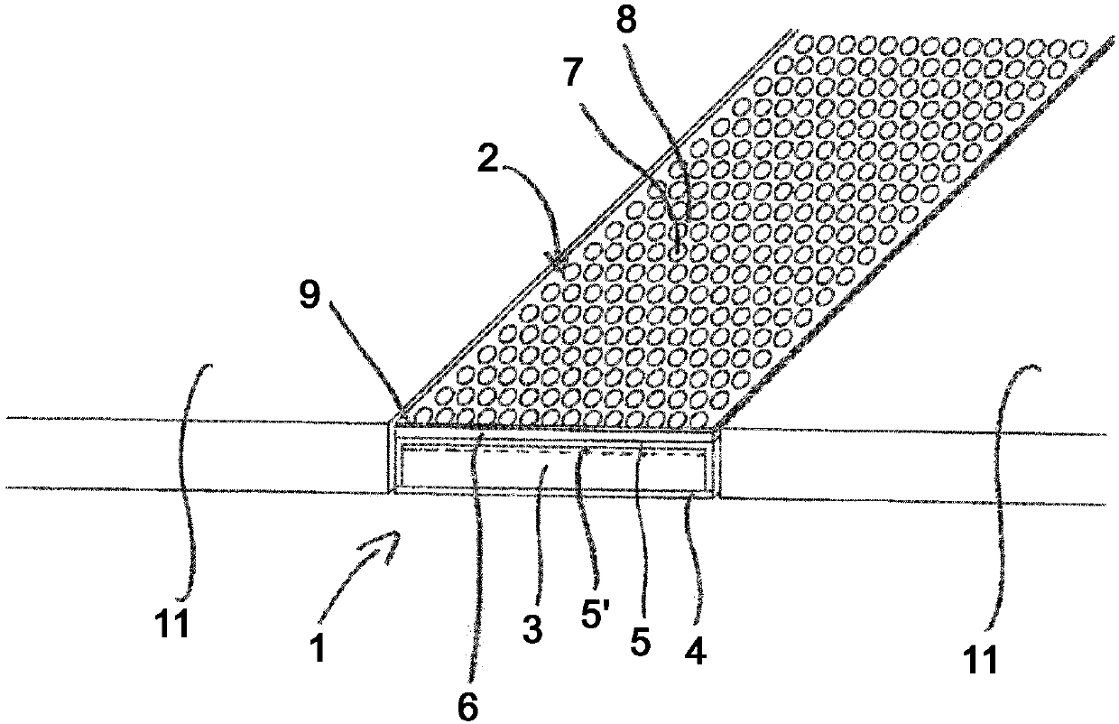
[0042] exist figure 1 A first embodiment of a device 10 according to the invention consisting of a bottom covering 11 and escape route markers 1 is schematically shown in . Here, the escape route marking 1 is embedded in the base covering 11 such that the outer side 2 of the escape route marking 1 is flush with the upper side of the base covering 11 , thereby forming an overall flat surface of the device 10 .

[0043] The escape route marking 1 comprises a lighting element 3 , which illuminates afterglow in the dark and is made of a photoluminescent material, the emitted light of which is emitted at the outer side 2 of the escape route marking 1 . A transparent protective element 5 surrounds the lighting element 3 and is thus arranged between the lighting element 3 and the outer side 2 , the transparent protective element surrounds the lighting element 3 together with the base element 4 . In this case, the protective element 5 and the base element 4 can be connected to one an...


PUM


Abstract

The invention relates to escape path markings for aircraft and to an assembly consisting of an escape path marking and a floor fitting. The escape path marking (1) for aircraft comprises a lighting element (3), which luminesces in the dark and the emitted light of which exits on an outer face (2) of the escape path marking (1), and a transparent protective element (5) arranged between the lightingelement (3) and the outer face (2) of the escape path marking (1). A flat grid element (6) which comprises regularly alternating pure color-transparent and opaque regions (7, 8) is provided between the lighting element (1) and the outer face (2) of the escape path marking (1). A transparent colored element is formed and arranged between the lighting element (3) and the outer face (2) of the escape path marking (1) such that a specified first hue is produced on the transparent regions (7) of the grid element (6) in the event of external lighting according to at least one specified lighting scenario on the outer face (2) of the escape path marking (1). The assembly (10) comprises an escape path marking (1) and a floor fitting (11) arranged adjacently to the escape path marking (1). The escape path marking (1) according to the invention is designed such that a pattern which is adapted to the pattern of the floor fitting (11) is produced when the assembly (10) is externally lit accordingto at least one specified lighting scenario on the outer face (2) of the escape path marking (1).

Description

technical field [0001] The invention relates to an escape route marking for an aircraft, and a device consisting of an escape route marking and a bottom covering. Background technique [0002] In commercial aircraft, it is absolutely essential to use an escape route marking system near the floor to indicate the way to emergency exits for passengers in the dark and in the event of an emergency in the event of cabin lighting failure. [0003] Besides electric drive systems, photoluminescent systems are also known for this purpose. These systems consist of strip-like elements that store energy from cabin lighting during normal operating conditions of the aircraft and re-emit it in the dark in the form of visible light. [0004] Since escape route markings are only used in emergency situations, it is of great interest to have as few markings as possible in the normal operating state of the aircraft. In addition to the purpose of an attractive design of the interior of the airc...

Claims


Application Information

Patent Timeline
Patent Type & Authority Applications(China)
IPC IPC(8): B64D47/02B64D11/00
CPCB64D2011/0038B60Q3/46B64D47/02B60Q3/54B64D11/00
Inventor 沃尔夫冈·祖特尔
Owner LUFTHANSA TECH AG
Why Eureka
Try Eureka