
Device for triggering the gas spring

A gas spring and trigger technology, which is applied in the direction of springs, gas shock absorbers, spring/shock absorbers, etc., can solve the problems of impossible adjustment of gas spring speed, difficult trigger measurement, etc., to achieve compact structure, durable and reliable manufacturing , Reliable clamping effect

Active Publication Date: 2020-10-16
吉多·万德施奈德
View PDF6 Cites 0 Cited by
  • Summary
  • Abstract
  • Description
  • Claims
  • Application Information

AI Technical Summary

Problems solved by technology

Such a configuration of the actuating mechanism has the great disadvantage that a great force is required for actuating the gas spring
In addition, there are other disadvantages: triggering can only be metered with difficulty, so that in the case of high triggering forces, adjustment of the gas spring speed is almost impossible

Method used


Image

  • Device for triggering the gas spring
  • Device for triggering the gas spring
  • Device for triggering the gas spring

Examples


Embodiment Construction

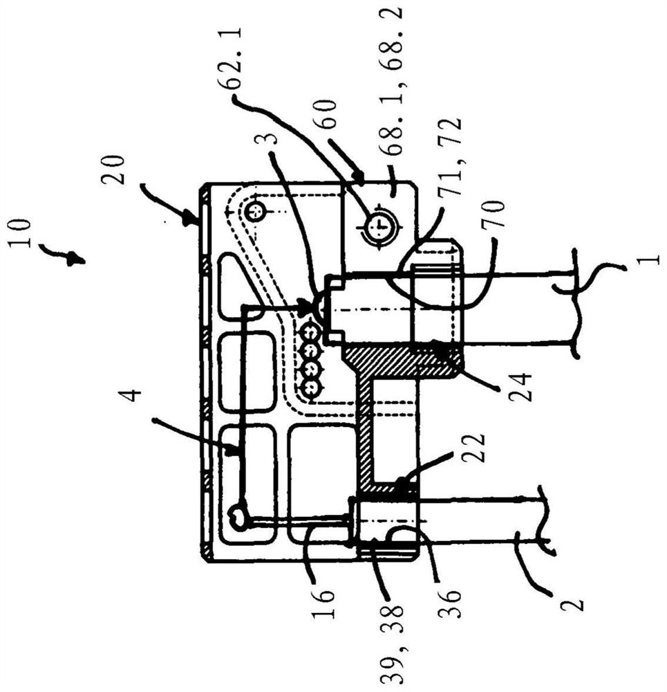
[0043] exist Figure 9 An exemplary use of the device 10 for activating a gas spring 1 for a seat 30 with an adjustable backrest 34 is shown schematically at a medium height. The backrest 34 is mounted rotatably about an axis of rotation 66 (arrow D) and is coupled to the gas spring 1 via a lever mechanism with a piston rod. In the inactive state of the device 10 , the gas spring 1 locks the swivel position of the backrest 34 via a lever mechanism. The device 10 is coupled via the actuating device 2 to the switching unit 32 and acts on the trigger of the gas spring. If the switching unit 32 is actuated, the device 10 acts on the trigger of the gas spring, whereby the rotational movement D of the backrest 34 is released. As soon as the switching unit 32 is deactivated, the gas spring 1 locks a further rotational movement D of the backrest 34 .

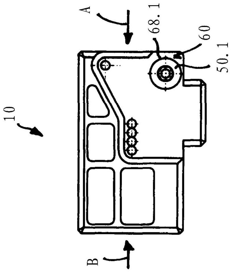
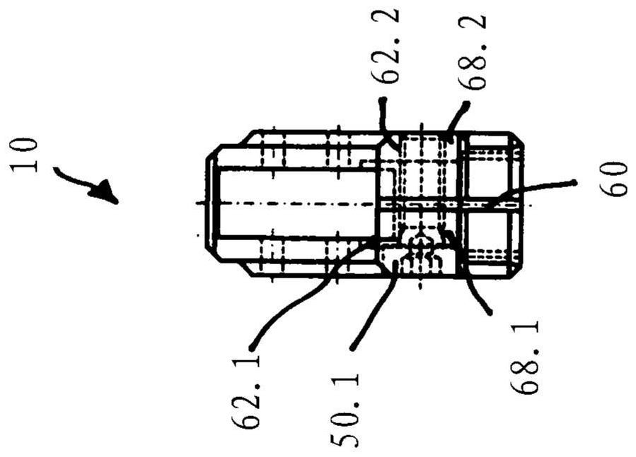
[0044] A first embodiment of a device 10 for triggering a gas spring is in Figures 1 to 4 is schematically shown in .

[0045] T...


PUM


Abstract

The invention relates to a device (10) for activating a gas spring (1), comprising: an actuating device (2); 3) The upper operating mechanism (4) and the housing (20), wherein the housing (20) has a gas spring connection gap (70), through which the upper end region of the gas spring (1) can In connection with the trigger ( 3 ) which extends into the housing ( 20 ), the gas spring connection recess ( 70 ) is formed as a continuous recess and there is an upper end introduced into the recess for clamping fixing of the gas spring ( 1 ) Mechanism in the upper region, characterized in that the housing (20) has an open slot (60) from the gas spring connection recess (70) to the outer end side (66) of the housing (20) and at least Partially extending over the length of the gas spring connection gap (70), the left and right protruding side wall regions (68.1, 68.2) are formed by the slot (60), and the left and right side wall regions ( 68.1, 68.2) there are mechanisms for clamping and fixing which tension the left and right side wall areas (68.1, 68.2) against one another, whereby the clamping force is applied to the gas spring (1 ) on the end region of the gas spring connection cavity (70).

Description

technical field [0001] The invention relates to a device for activating a gas spring, comprising: an actuating device; an actuating means, operatively connected to the actuating device, acting on an end-side trigger of the gas spring, wherein the actuating means is indirectly or directly act on the trigger and in particular constitute a lever device with reducing or increasing force and / or displacement of the actuating lever, said lever device is operatively connected to the actuating device and at least has a direct or indirect cooperating effect with the actuating lever The trigger lever, the trigger lever acts on the trigger; and comprises a housing, the housing has a gas spring connection gap, through which the upper end region of the gas spring can be passed through to the housing The inner trigger connection, the gas spring connection recess is formed as a continuous recess, in particular with an internal thread, and there are means for clamping the upper end region of t...

Claims


Application Information

Patent Timeline
Patent Type & Authority Patents(China)
IPC IPC(8): F16F9/02
CPCF16F9/0245F16C1/10F16F9/0263F16F2230/186
Inventor 吉多·万德施奈德
Owner 吉多·万德施奈德
Learn More