
Electrical connector and manufacturing method thereof

A technology for electrical connectors and manufacturing methods, applied in the field of electrical connectors, can solve problems such as serious signal crosstalk and difficulty in meeting high-speed transmission requirements, and achieve the effects of improving resonance point, ensuring high-frequency signal transmission performance, and simple manufacturing process

Active Publication Date: 2018-09-18
ALL BEST ELECTRONICS TECH CO LTD
View PDF5 Cites 0 Cited by
  • Summary
  • Abstract
  • Description
  • Claims
  • Application Information

AI Technical Summary

Problems solved by technology

However, during the high-frequency analysis of the existing USB Type-C connector, it was found that the resonance point of the frequency domain parameters of the connector exceeded the specification, and the signal crosstalk of the differential signal terminals used for high-frequency signal transmission was relatively serious, which was difficult to meet High-speed transmission requirements

Method used


Image

  • Electrical connector and manufacturing method thereof
  • Electrical connector and manufacturing method thereof
  • Electrical connector and manufacturing method thereof

Examples


Embodiment Construction

[0024] The present invention will be described in detail below in conjunction with various embodiments shown in the drawings. However, these embodiments do not limit the present invention, and any structural, method, or functional changes made by those skilled in the art according to these embodiments are included in the protection scope of the present invention.

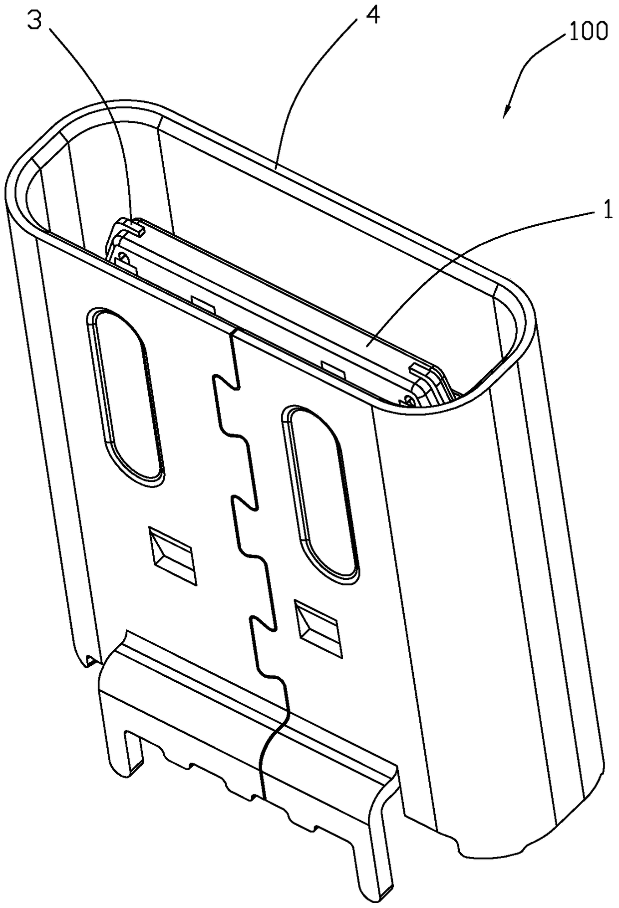
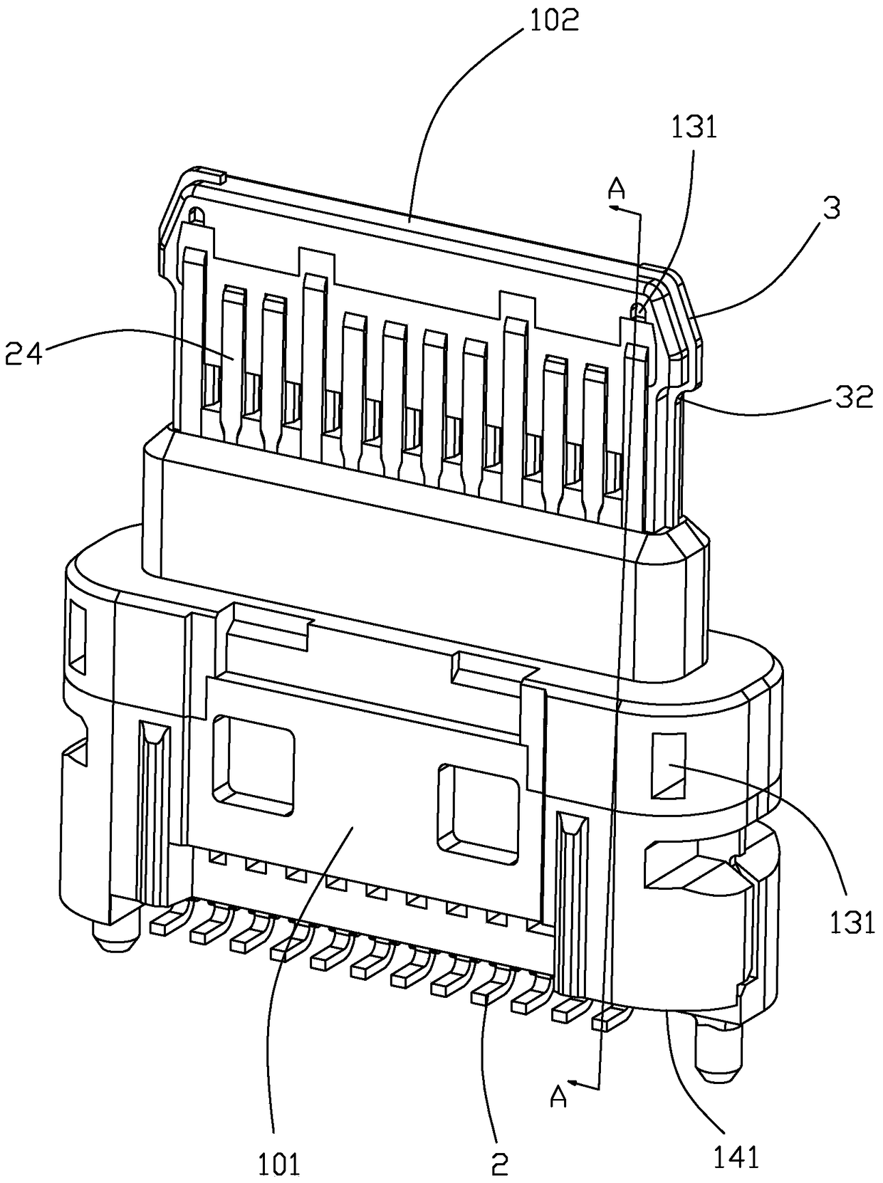
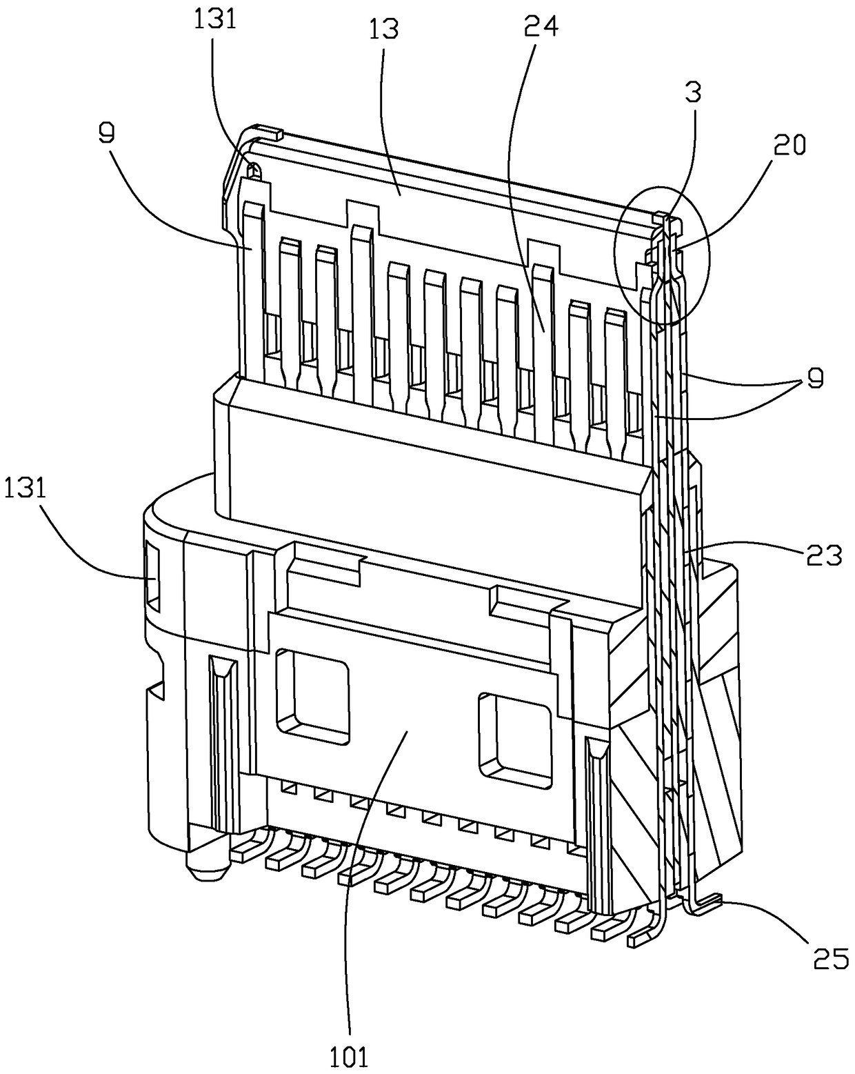
[0025] Please refer to Figure 1 to Figure 9 Shown is a preferred embodiment of the electrical connector 100 of the present invention. The electrical connector 100 of the present invention includes a terminal base 1, conductive terminals 2 disposed in the terminal base 1 in two rows, a metal shielding sheet 3 disposed between the two rows of conductive terminals 2, and a shielding shell covering the periphery of the terminal base 1 4. The two rows of conductive terminals 2 include a plurality of first terminals 21 arranged in one row and a plurality of second terminals 22 arranged in the other row. The metal shie...


PUM


Abstract

The invention provides an electrical connector and a manufacturing method thereof. The electrical connector comprises a terminal base, conductive terminals arranged inside the terminal base in two rows and a metal shielding sheet arranged between the two rows of conductive terminals. The two rows of conductive terminals include at least one grounding terminal. At least one of the grounding terminal and the metal shielding sheet is provided with a press-against portion which protrudes towards the other one and enables the both to press against each other, the terminal base comprises an insulating body which is formed on the periphery of the press-against portion of the grounding terminal and the metal shielding sheet by injection molding to keep the grounding terminal and the metal shielding sheet in a press-against state at the press-against portion, and the insulating body is provided with a yielding hole for a pressing mechanism to press against and fix the press-against portion during injection molding so that the grounding terminal and the metal shielding sheet are in tight contact.

Description

technical field [0001] The invention relates to an electrical connector, in particular to an electrical connector capable of high-speed data transmission. Background technique [0002] As a new generation product of USB 3.0 connector, the USB Type-C connector not only no longer has a directional plug interface, that is, the plug connector can be inserted into the socket connector in both directions, but also supports a data transmission speed of 10Gbit / s . The USB Type-C connector includes a plastic base and two rows of conductive terminals arranged on the plastic base. The conductive terminals include ground terminals and differential signal terminals adjacent to the ground terminals for high-speed transmission and data reception. However, during the high-frequency analysis of the existing USB Type-C connector, it was found that the resonance point of the frequency domain parameters of the connector exceeded the specification, and the signal crosstalk of the differential ...

Claims


Application Information

Patent Timeline
Patent Type & Authority Patents(China)
IPC IPC(8): H01R13/40H01R13/02H01R43/18H01R43/20
Inventor 彭易平
Owner ALL BEST ELECTRONICS TECH CO LTD
Learn More