Dual Broadband Dual Polarized Omnidirectional Ceiling Antenna
A ceiling-mounted antenna and dual-polarization technology, which is applied to antennas, electrical components, and radiation element structures, can solve the problems of incomplete compatibility and support, and achieve the effect of increased bandwidth and increased antenna radiation area
- Summary
- Abstract
- Description
- Claims
- Application Information
AI Technical Summary
Problems solved by technology
Method used
Image
Examples
Embodiment 1
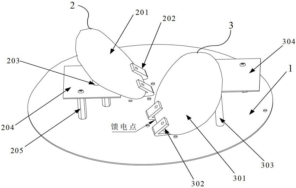
[0037] figure 1 A schematic structural diagram of the dual-broadband dual-polarized omnidirectional ceiling antenna in Embodiment 1 of the present invention is shown. Such as figure 1 As shown, the dual-broadband dual-polarized omnidirectional ceiling antenna includes: a circular reflector 1 and a first plate-shaped oscillator 2 and a second plate-shaped oscillator 3 arranged on the reflector 1 and orthogonal to each other.
[0038] The first chip vibrator 2 includes a first radiation plate 21 and a first fixing seat 22 . in,
[0039]The first radiating plate 21 is obliquely arranged on the reflecting plate 1 for transmitting and receiving electromagnetic wave signals, and the included angle between its radiating surface and the top surface of the reflecting plate 1 is 30°-60°. The first radiation plate 21 is fixed on the reflection plate 1 through the first fixing base 22 . The first fixing seat 22 is an angle steel with an acute angle, one side of which is fixed to the r...
Embodiment 2
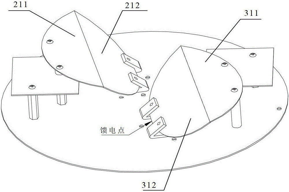
[0055] The structure of the dual broadband dual polarization omnidirectional ceiling antenna in embodiment 2 is similar to the structure of the dual broadband dual polarization omnidirectional ceiling antenna in embodiment 1, the difference is that the first sheet vibrator 2 in this embodiment The structures of the first radiating plate of the first radiating plate and the second radiating plate of the second chip oscillator 3 are different from those of the first radiating plate of the first chip oscillator 2 and the second radiating plate of the second chip oscillator 3 in Embodiment 1. figure 2 A schematic structural diagram of the dual-broadband dual-polarized omnidirectional ceiling antenna in Embodiment 2 is shown. Such as figure 2 As shown, the first radiating plate 21 of the first chip vibrator 2 and the second radiating plate 31 of the second chip vibrator 3 are bent once on the basis of the first embodiment. The first radiating plate 21 in this embodiment includes...
Embodiment 3
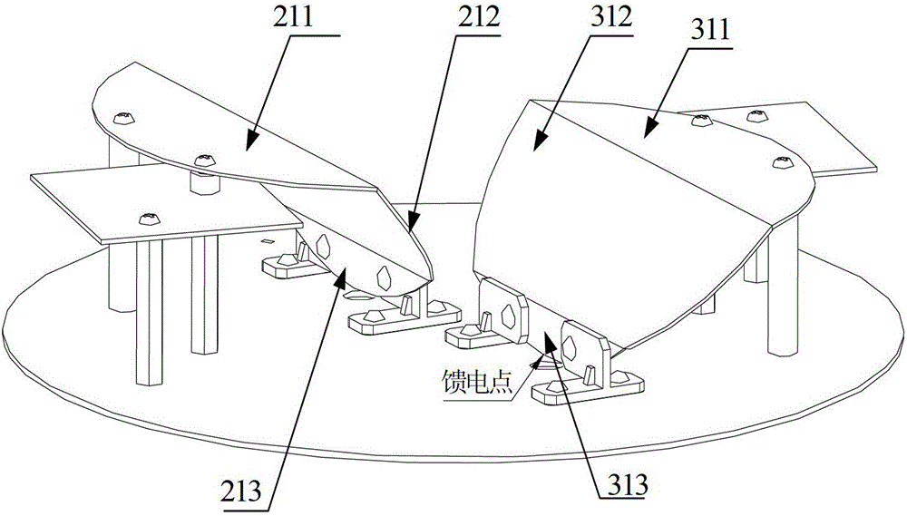
[0064] The structure of the dual broadband dual polarization omnidirectional ceiling antenna in embodiment 3 is similar to the structure of the dual broadband dual polarization omnidirectional ceiling antenna in embodiment 2, the difference is that in this embodiment the first sheet vibrator The first radiating plate 21 of 2 and the second radiating plate 31 of the second chip vibrator 3 are bent twice. image 3 A schematic structural diagram of the dual-broadband dual-polarized omnidirectional ceiling antenna in Embodiment 3 is shown. Such as image 3 As shown, the first radiant plate 21 in this embodiment includes a first bent portion 211, a second bent portion 212, and a fifth bent portion 213, and the second radiant plate 31 includes a third bent portion 311, a fourth bent portion The bent portion 312 and the sixth bent portion 313 .
[0065] The first bent part 211 is parallel to the reflector 1, the angle between the radiation surface of the second bent part 212 and th...
PUM
 Abstract
Description
Claims
Application Information
 - R&D
- Intellectual Property
- Life Sciences
- Materials
- Tech Scout
- Unparalleled Data Quality
- Higher Quality Content
- 60% Fewer Hallucinations
Browse by: Latest US Patents, China's latest patents, Technical Efficacy Thesaurus, Application Domain, Technology Topic, Popular Technical Reports.
© 2025 PatSnap. All rights reserved.Legal|Privacy policy|Modern Slavery Act Transparency Statement|Sitemap|About US| Contact US: help@patsnap.com


