Textile technology

A technology, the technology of the traveler, which is applied in the direction of textiles and papermaking, can solve the problems of labor loss, increased power consumption, and delay in production, and achieve the effects of reducing equipment weight and cost, reducing friction, and avoiding collar loss.

Pending Publication Date: 2021-12-31
良明(天津)科技有限公司 +1
View PDF0 Cites 0 Cited by
  • Summary
  • Abstract
  • Description
  • Claims
  • Application Information

AI Technical Summary

Problems solved by technology

[0002] Steel collars and travellers in spinning equipment in the textile machinery industry have been traditionally used for 200 years since they have been in the textile industry for 200 years. The frictional resistance of mutual sliding operation is large, the wear is serious and the life is short. Basically, the traveler needs to be shut down once a week, and the steel ring is replaced once a year or two. Not only will the production be delayed during the replacement, but also it will run at a slow speed for half a day after changing the traveler, resulting in production loss, labor loss, replacement labor costs, material costs, etc. The imported traveler is nearly ten times the price of the domestic traveler and needs to be replaced within a month
The sliding friction resistance between the traveler and the steel ring is very large, which limits the number of spinning. The sliding friction is proportional to the square of the speed, the power consumption is doubled, and the steel ring is also worn out quickly. The combination of steel ring and traveler is replaced every year. The loss is 20 times the loss of direct material costs. Although it is already ignored, it needs to be solved urgently! There is also no structure and technology that realizes the front roller, electric spindle and electric traveler through electronic intelligent control so far.

Method used


Image

  • Textile technology
  • Textile technology
  • Textile technology

Examples


Embodiment 1

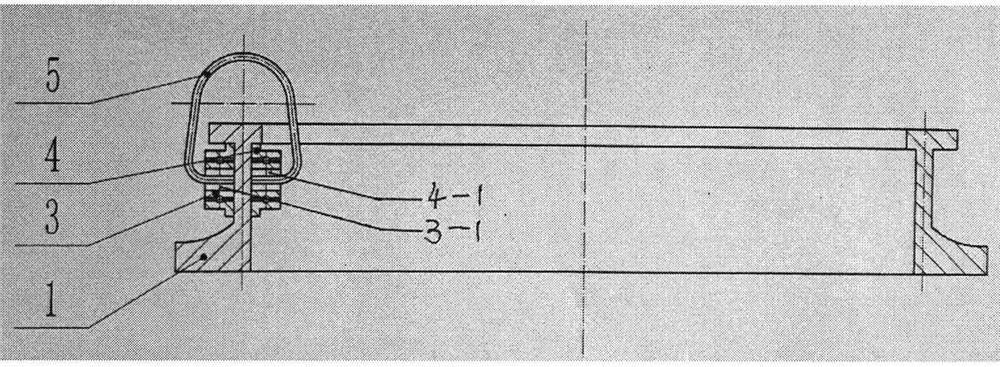
[0009] Both ends of the traveler adopt double bearings or use wear-resistant material wheel system, which is easy to modify, takes less time and has a longer service life. It is most suitable for the transformation of existing factories, and the existing steel ring is used. The traveler only needs to install the two ends of the original traveler. Wear-resistant material wheels or bearings are also available, but because the original steel wire (belt) ring is too small, it is inconvenient to install the wheel, so it is processed with steel wire, and the ring can be slightly longer to facilitate installation and threading, so that the steel traveler is really made of steel wire and round The century-old dream of the textile industry, light in weight, easy to process, and low in cost. The two ends of the c-shaped traveler are equipped with bearings and special sleeves are installed in the middle. The convex part can also be equipped with wear-resistant material rollers, and the rin...

Embodiment 2

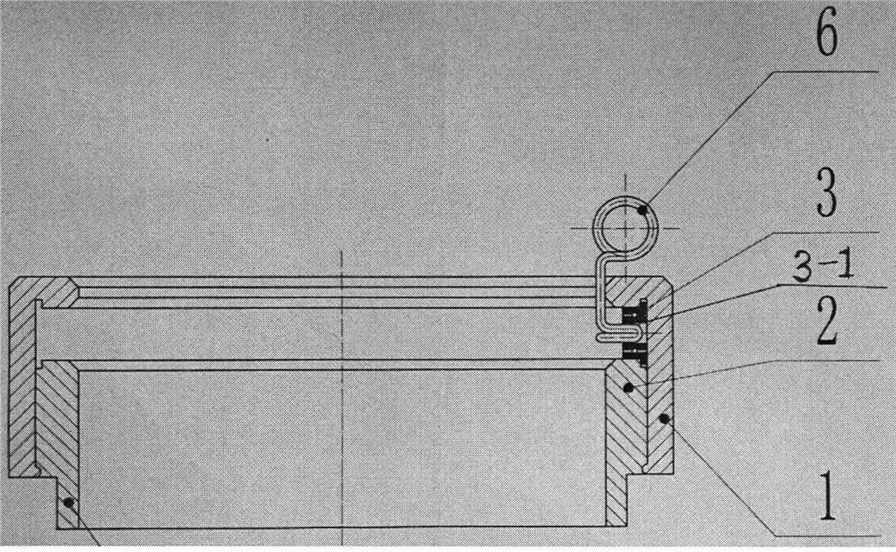
[0011] Due to the heavy weight and high cost of the double bearings, the threading efficiency of the closed yarn of the traveler is low, and the front roller cannot be stopped alone, and a lot of cotton yarn will be wasted if it cannot penetrate the traveler in time and quickly so that the yarn can be wound quickly. The single-bearing upper and lower circular track structure is adopted, and The lower track can be disassembled to reduce bearing cost and resistance design. The e-type open pigtail wire hook is adopted. The other end of the wire hook is inserted into the inner hole of the bearing through a special sleeve to fix it. At the same time, the steel ring is also modified accordingly, and the steel ring is appropriately increased. The inner diameter of the collar makes the single spindle more entangled and reduces the number of yarn changes. Corresponding to the inner side of the inner slideway of the original steel ring, a recessed groove is processed as the upper track of...

Embodiment 3

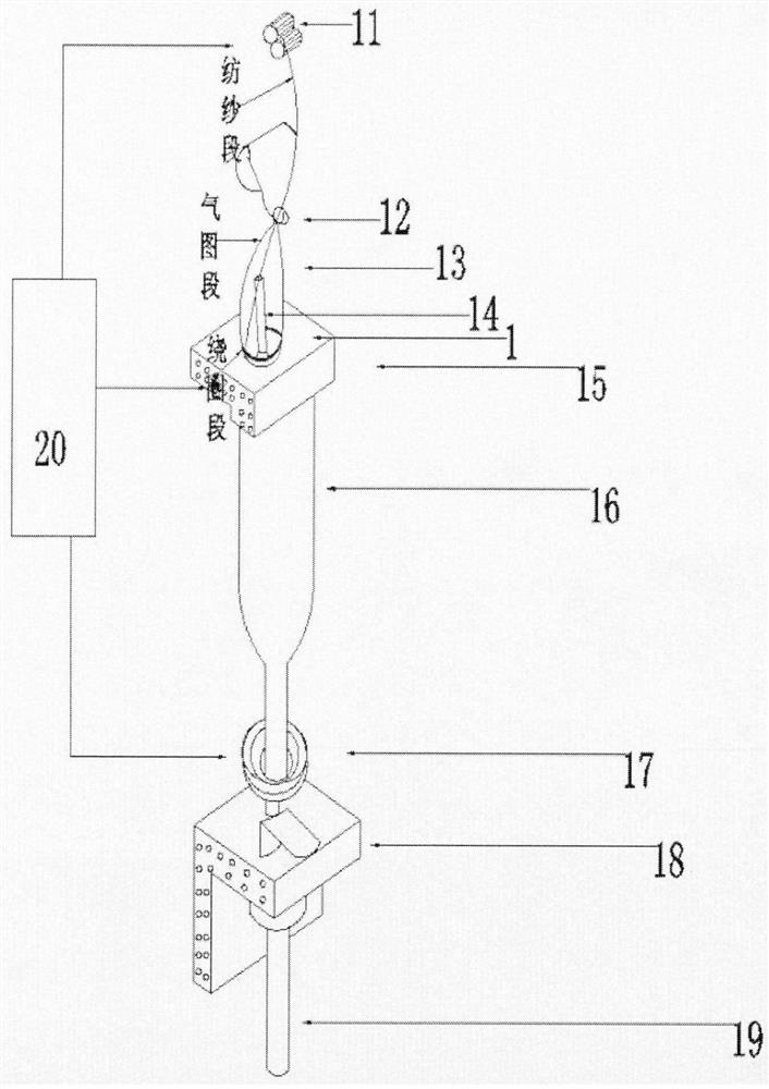
[0013] On the basis of the single bearing track, add a bearing in series before or after the original bearing, connect it with a g-shaped pigtail hook and install a permanent magnet (rotor) to realize electric and active wire hooks. Yarn hanging avoids the difficulty of the traveler moving when threading the yarn, and greatly improves the efficiency of the car operator. Since the traveler in Embodiment 1 and 2 is passive, it is not conducive to spinning worsted yarn. Twisting resistance limits the fineness of the spinnable yarn and line speed, so this embodiment is characterized in that the active traveler design is adopted, the electric traveler adopts a special structural design, the linear motor ring is made, the embedded shaftless motor is used, and high-frequency magnetic materials are used to make ( Rotor) rail car has reached high speed and low consumption. See image 3


PUM


Abstract

The invention discloses a textile technology. Sliding of a steel wire ring and a steel collar is changed into a rolling connection structure, double bearings or rollers are additionally arranged at the joint of the steel wire ring and the steel collar, e-shaped and g-shaped single-bearing left-right open hook structures are adopted, and yarn can be hung by the left hand and the right hand independently, so that the efficiency of knitters is greatly improved; and a motor is embedded in the steel collar to make the steel wire ring and a steel collar plate changed into an active type, a mechanical spindle in centralized mechanical transmission is replaced with an electric spindle driven by a direct-current brushless axial motor, front and rear rollers are achieved through an artificial intelligence control 1D technology, and an electric spindle 1D technology is optimally coordinated with an electric steel wire ring 1D technology and an electric steel collar plate 1D technology to achieve 4D spinning, so that the quality and the efficiency are improved.

Description

technical field [0001] This technology belongs to the textile machinery industry, the core device in the spinning equipment. Background technique [0002] Steel collars and travellers in spinning equipment in the textile machinery industry have been traditionally used for 200 years since they have been in the textile industry for 200 years. The frictional resistance of mutual sliding operation is large, the wear is serious and the life is short. Basically, the traveler needs to be shut down once a week, and the steel ring is replaced once a year or two. Not only is the production delayed during the replacement, but also the traveler has to run at a slow speed for half a day after the traveler is replaced, resulting in production loss, labor loss, replacement labor costs, material costs, etc. The imported traveler is nearly ten times the price of the domestic traveler and needs to be replaced within a month. The sliding friction resistance between the traveler and the steel r...

Claims


Application Information

Patent Timeline
Patent Type & Authority Applications(China)
IPC IPC(8): D01H7/60
CPCD01H7/606D01H7/602D01H7/604
Inventor 赵宇光杨阳其他发明人请求不公开姓名
Owner 良明(天津)科技有限公司
Why Eureka
Try Eureka