Assembly of spinning equipment

A component and equipment technology, applied in textiles and papermaking, etc., can solve the problems of wear of traveler and ring, affecting yarn quality, short life, etc., to achieve the effect of reducing friction, avoiding collar slipping, and high elasticity

Pending Publication Date: 2021-12-31
良明(天津)科技有限公司 +1
View PDF0 Cites 0 Cited by
  • Summary
  • Abstract
  • Description
  • Claims
  • Application Information

AI Technical Summary

Problems solved by technology

[0003] In order to overcome the existing deficiencies, the present invention provides a component of spinning equipment, which aims to reduce the friction between components, reduce the force and vibration of the yarn, improve the service life of the components, improve the quality of the yarn, and solve the problem of existing steel wire Rings and rings are severely worn, life is short, and yarn quality is affected

Method used


Image

  • Assembly of spinning equipment
  • Assembly of spinning equipment
  • Assembly of spinning equipment

Examples


Embodiment 1

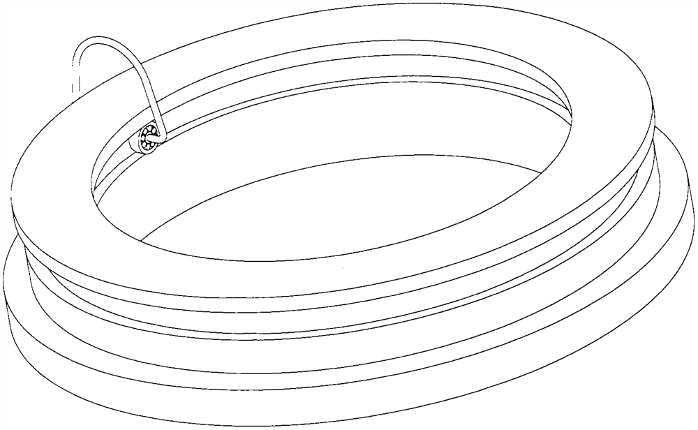
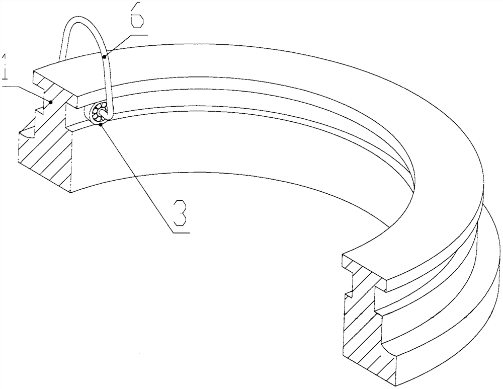
[0031] See attached figure 1 , 2 , the present embodiment adopts C-type or human-shaped traveler plus double bearings.

[0032] A component of spinning equipment, including a steel ring 1 and a traveler 6, the steel ring is in the shape of a ring, the traveler is a C-shaped traveler, and a bearing 3 is installed at the connection between the traveler and the steel ring, that is, at the end of the traveler. like Figure 8 , 9 , the two ends of the traveler are equipped with bearings, and the two bearings are coaxially opposite to each other; the steel ring is provided with a circular track 4 suitable for the bearing; the traveler is connected to the track through the bearings. When working, the traveler And the bearing slides along the track on the steel ring. It is also possible to add a special cover respectively in the middle of the c-shaped steel traveler two end bearings, and install a roller made of wear-resistant material on the convex top of the c-shaped steel trave...

Embodiment 2

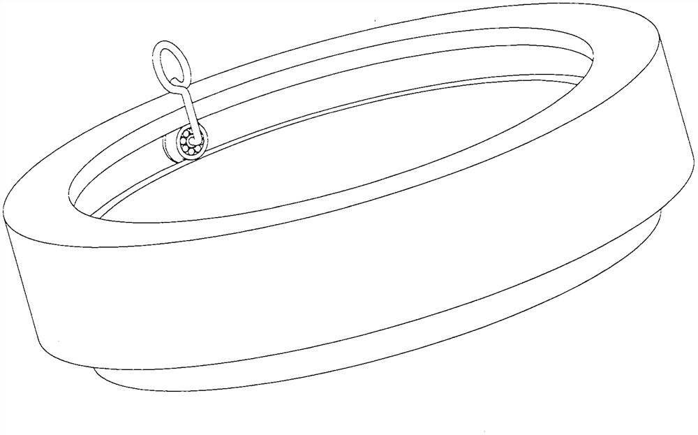
[0036] See attached image 3 , 4 , In this embodiment, an e-type steel traveler and a single bearing are used.

[0037] On the basis of Embodiment 1, in this embodiment, the steel ring is a split type, including the steel ring body 1 and the steel ring lower ring 2. The ring body and the steel ring lower ring are provided with grooves to form the bearing 3 and the wheel rim 31. Compatible circular track 4; such as Figure 10 , the traveler is an e-shaped pigtail wire hook, the upper part of the traveler 6 is helical and has an opening 61, the lower end of the traveler is equipped with a bearing, and the outer edge of the bearing is provided with a rim 31; insert the other end of the wire hook through a special sleeve The inner hole of the bearing is fixed, and the bearing is placed in the circular track. The ring body and the lower ring of the ring are fixedly connected by common methods such as buckle or screw.

[0038] The upper and lower circular track structure of sing...

Embodiment 3

[0041] See attached Figure 6 , 7 , 8, the present embodiment adopts parallel double g type pigtail steel wire to hook and add double bearing.

[0042] On the basis of Embodiment 2, in this embodiment, the traveler 6 adopts a parallel g-type pigtail wire hook, and the traveler is a parallel g-type pigtail wire hook whose tails are connected, and the two g-type pigtail wire hooks are in the same cylindrical surface Longitudinally juxtaposed; the upper part of the traveler 6 is helical and provided with an opening 61; the two g-shaped wire hooks adopt a left and right unscrewing structure; the double-folding and rotating bearing at the connection between the traveler and the steel ring; the lower ring of the steel ring is provided with a ring Cavity 21, the annular coil 7 is embedded in the annular cavity 21 of the lower ring of the steel collar, and the annular coil is equipped with a magnetizer ring 8 embedded in the annular cavity 21; the permanent magnet 9 corresponding to ...


PUM


Abstract

The invention discloses an assembly of spinning equipment. The assembly comprises a ring-shaped steel collar and a steel wire ring; the steel collar is provided with a steel wire ring track; the steel wire ring is movably connected to the track; the steel wire ring slides along the track during working; the assembly is characterized in that bearings are additionally arranged at the joint of the steel wire ring and the steel collar; the steel collar is provided with an annular track matched with the bearings; a coil is embedded on the steel collar to serve as a stator; a permanent magnet is installed on a steel wire hook to serve as a rotor; and a shaftless motor is formed. Sliding of the steel wire ring and the steel collar is changed into a rolling connection structure, double bearings or rollers are additionally arranged at the joint of the steel wire ring and the steel collar, and e-type and g-type single-bearing left-right open hook structures are adopted, so that the efficiency of knitters is greatly improved; and the motor is embedded into the steel collar to make the steel wire ring and a steel collar plate changed into an active type, so that cost and weight are reduced, and electricity and energy can be saved.

Description

technical field [0001] This technology belongs to the textile machinery industry, the core device in the spinning equipment. Background technique [0002] The steel ring and traveler in the spinning equipment of the textile machinery industry are the key components on the spinning frame, and the performance directly affects the twist, package density, yarn breakage and hairiness of the yarn. The traditional steel traveler and steel ring have been matched since weaving for 200 years. The two are mutually sliding and running, with high frictional resistance and severe wear and short life. At high speed, the contact surface between the traveler, the steel ring and the yarn is subject to high friction, especially the inner side of the traveler, which is severely worn under the action of centrifugal force, and the traveler needs to be shut down to replace the traveler basically once a week , changing the steel ring every one or two years not only delays the production during the...

Claims


Application Information

Patent Timeline
Patent Type & Authority Applications(China)
IPC IPC(8): D01H7/58D01H7/60
CPCD01H7/58D01H7/604
Inventor 刘晓鸣翟科其他发明人请求不公开姓名
Owner 良明(天津)科技有限公司
Why Eureka
Try Eureka