Automatic wave peak welding equipment

A wave soldering and equipment technology, which is applied in the field of automated wave soldering equipment, can solve problems such as inability to solder double-sided plug-ins or mixed PCB products, and achieve the effect of improving production efficiency

Pending Publication Date: 2018-05-15
深圳市浩宝技术有限公司
View PDF0 Cites 3 Cited by
  • Summary
  • Abstract
  • Description
  • Claims
  • Application Information

AI Technical Summary

Problems solved by technology

[0004] The technical problem to be solved by the present invention is to provide an automatic wave soldering equipment, which aims to solve the problem that the existing wave soldering equipment cannot solder double-sided plug-ins or mixed PCB products

Method used


Image

  • Automatic wave peak welding equipment
  • Automatic wave peak welding equipment
  • Automatic wave peak welding equipment

Examples


Embodiment Construction

[0023] Now in conjunction with the accompanying drawings, the preferred embodiments of the present invention will be described in detail.

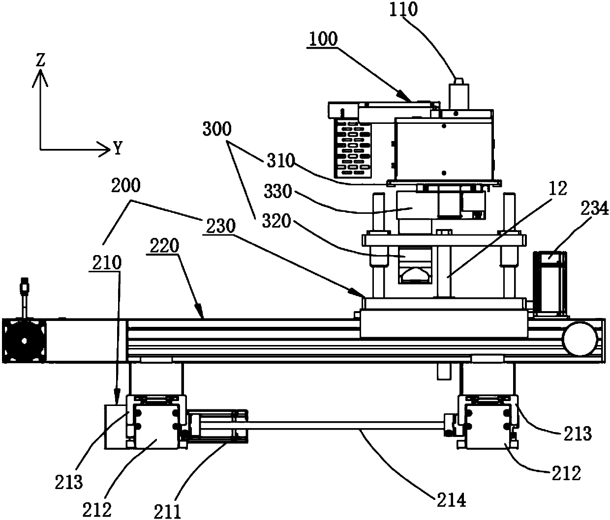
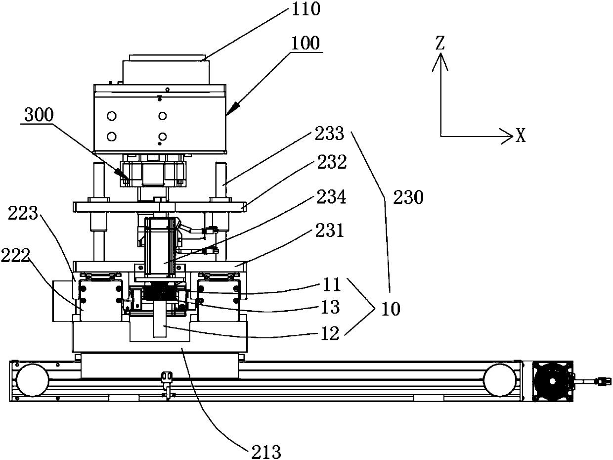
[0024] Such as figure 2 As shown, the present invention provides an automatic wave soldering equipment, including a tin furnace 100 and a nozzle 110 located on the tin furnace 100, the wave soldering equipment also includes a three-dimensional mobile device 200, the tin furnace 100 is installed on the three-dimensional mobile device 200, and the three-dimensional The moving device 200 drives the tin furnace 100 and the nozzle 110 to move along the X-axis direction, the Y-axis direction and the Z-axis direction respectively. The three-dimensional moving device 200 drives the tin furnace 100 to move along the X-axis direction, the Y-axis direction, and the Z-axis direction respectively, and then drives the nozzle 110 to avoid the parts to be protected, and accurately reach the position where the PCB product is to be soldered, so as to reali...


PUM


Abstract

The invention relates to automatic wave peak welding equipment. The automatic wave peak welding equipment comprises a tin furnace, and a nozzle arranged on the tin furnace. The wave peak welding equipment further comprises a three-dimensional moving device; the tin furnace is mounted on the three-dimensional moving device; and the three-dimensional moving device drives the tin furnace and the nozzle to move in an X-axle direction, a Y-axle direction and a Z-axle direction. As the three-dimensional moving device drives the tin furnace and the nozzle to move in the X-axle direction, the Y-axle direction and the Z-axle direction, the nozzle is driven to avoid from protected parts to precisely reach welded positions of PCB products to realize selective welding of double-surface inserts or mixed PCB products; and the nozzle is flexibly controlled to greatly improve the production efficiency.

Description

technical field [0001] The invention relates to the technical field of wave soldering, in particular to an automatic wave soldering equipment. Background technique [0002] Wave soldering is currently a more commonly used electronic plug-in packaging process equipment. Its principle is to pass the PCB board inserted with electronic components through a special transmission mechanism, and pass through various process systems according to the set speed, so that the soldering surface of the PCB board and the high-temperature liquid tin contact to achieve the purpose of welding. [0003] Such as figure 1 As shown, the wave soldering method in the market is generally soldered by contacting the entire soldering surface 1 of the PCB product with the wave surface 3 of the tin furnace 2 . However, with the wide application of patch and plug-in mixed PCB products, SMD patch components are usually soldered by reflow soldering, and the remaining plug-in components can only be made int...

Claims


Application Information

Patent Timeline
IPC IPC(8): B23K3/00B23K1/08
CPCB23K1/085B23K3/00
Inventor 罗文欣
Owner 深圳市浩宝技术有限公司
Why Eureka
Try Eureka