Cutter staggered double-face engraving machine

An engraving machine and double-sided technology, which is applied in the field of double-sided engraving machines, can solve the problems of affecting production efficiency and collision between upper and lower knives, and achieve the effects of reducing equipment cost, avoiding knife collision, and improving processing efficiency

Pending Publication Date: 2018-05-15
NANTONG YUETONG CNC EQUIP CO LTD
View PDF0 Cites 1 Cited by
  • Summary
  • Abstract
  • Description
  • Claims
  • Application Information

AI Technical Summary

Problems solved by technology

Therefore, it is necessary to adopt the method of double-sided engraving. In the existing double-sided engraving machine, the upper and lower movable knives run synchronously in the Y-axis direction, and the center of the tool is coaxial, so it is easy to produce the collision phenomenon of the upper and lower knives; will affect production efficiency

Method used


Image

  • Cutter staggered double-face engraving machine
  • Cutter staggered double-face engraving machine
  • Cutter staggered double-face engraving machine

Examples


Embodiment 1

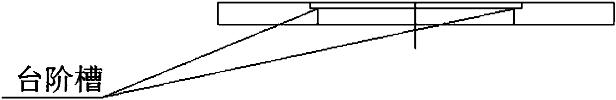
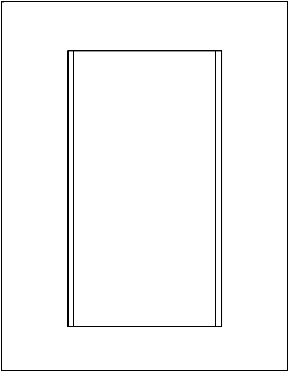
[0028] This embodiment needs to process the step groove used to fix the glass in the middle of the wooden door, such as Figure 1-2 As shown, the following double-sided engraving machines were used:

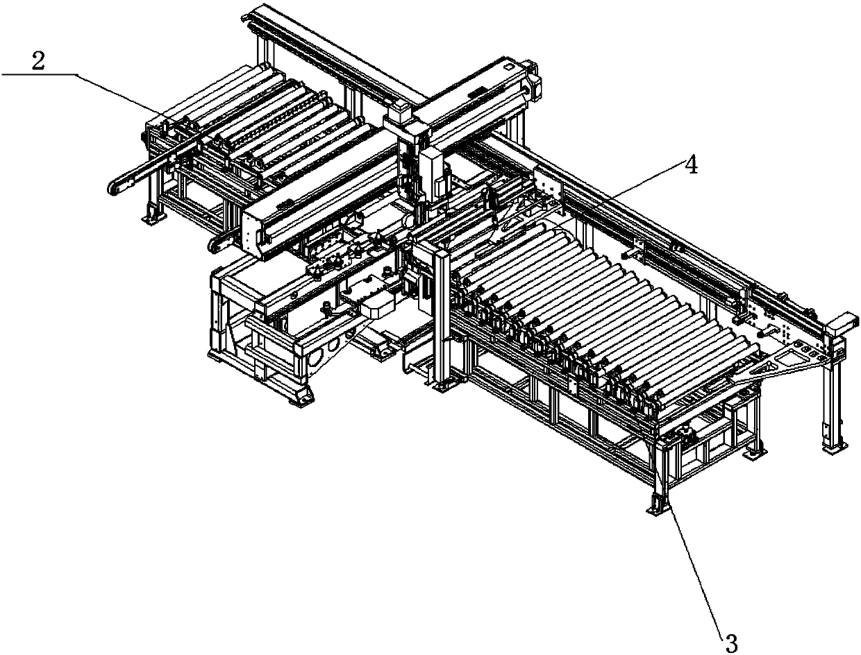
[0029] see Figure 3-Figure 6 , a double-sided engraving machine with cutter dislocation, comprising a feed table 2 and a discharge table 3, the sample feed table and the sample discharge table are arranged along the X axis, and there is a set between the sample feed table and the sample discharge table along the Y axis. The upper processing unit and the lower processing unit; the upper processing unit is located at the upper part of the Z axis, and the lower processing unit is located at the lower part of the Z axis; the respective Z-axis cutter heads on the upper and lower processing units are misaligned in the Y-axis direction during the cutting process; X axis is perpendicular to the Y axis, and the Z axis is perpendicular to the XOY plane.

[0030] In this embodiment, the ...

Embodiment 2

[0033] The processed workpiece of the present embodiment is likewise Figure 1-2 Wooden door shown with step-slot opening for glass.

[0034] see image 3 and Figure 7 , a double-sided engraving machine with tool dislocation, comprising a sample inlet 2 and a sample outlet 3, the sample inlet and the sample outlet are arranged along the X-axis, and there is a set between the sample inlet and the sample outlet along the Y-axis The upper processing unit and the lower processing unit; the upper processing unit is located at the upper part of the Z axis, and the lower processing unit is located at the lower part of the Z axis; the respective Z-axis cutter heads on the upper and lower processing units are misaligned in the Y-axis direction during the cutting process; X axis is perpendicular to the Y axis, and the Z axis is perpendicular to the XOY plane.

[0035] Such as Figure 7 As shown, the upper processing unit and the lower processing unit adopt the same Y-axis power sou...


PUM


Abstract

The invention relates to a cutter staggered double-face engraving machine. The cutter staggered double-face engraving machine comprises an upper processing unit and a lower processing unit which are arranged along the Y axis. The upper processing unit is located on the upper portion of the Z axis. The lower processing unit is located on the lower portion of the Z axis. Z-axis cutter heads of the upper processing unit and the lower processing unit are staggered in the Y-axis direction in the cutting process. The X axis is perpendicular to the Y axis. The Z axis is perpendicular to an XOY plane.According to the cutter staggered double-face engraving machine, cutters are staggered in the Y-axis direction, power is separated, upper and lower cutter steps conduct processing on the two sides correspondingly, and the phenomenon that the upper and lower cutters collide each other cannot occur.

Description

technical field [0001] The invention relates to a double-sided engraving machine, which belongs to the technical field of double-sided engraving machines. Background technique [0002] In the processing process of existing wooden door leaves, some products require engraving machine to carve a door opening for installing glass or door core board. In order to facilitate the installation of glass or door core board, a step or special-shaped edge is required on the edge of the door opening. Therefore, it is necessary to adopt the method of double-sided engraving. In the existing double-sided engraving machine, the upper and lower movable knives run synchronously in the Y-axis direction, and the center of the tool is coaxial, so it is easy to produce the collision phenomenon of the upper and lower knives; If it is carried out, it will affect the production efficiency. Contents of the invention [0003] The object of the present invention is to provide a double-sided engraving ...

Claims


Application Information

Patent Timeline
Patent Type & Authority Applications(China)
IPC IPC(8): B44B1/00B44B1/06
CPCB44B1/003B44B1/06B44B2700/12
Inventor 周娟张海建陆春伟储春松
Owner NANTONG YUETONG CNC EQUIP CO LTD
Why Eureka
Try Eureka