Monitoring camera mount

A technology for monitoring cameras and supporting frames, which is applied in the directions of machines/brackets, supporting machines, mechanical equipment, etc., which can solve problems such as trouble, the angle and height cannot be adjusted to the best position, and the use is inconvenient.

Active Publication Date: 2018-05-15
重庆好客信息科技有限公司
View PDF7 Cites 6 Cited by
  • Summary
  • Abstract
  • Description
  • Claims
  • Application Information

AI Technical Summary

Problems solved by technology

[0002] Surveillance camera support frame refers to the equipment used to fix the position of security monitoring equipment. Most of the support frames currently used are brackets with fixed shapes and angles. Sometimes when in use, the angle and height cannot be adjusted to the best position, which is extremely inconvenient to use. Moreover, when changing the monitoring position in a small range, it needs to be re-fixed, which is troublesome

Method used


Image

  • Monitoring camera mount
  • Monitoring camera mount
  • Monitoring camera mount

Examples


Embodiment Construction

[0022] The following will clearly and completely describe the technical solutions in the embodiments of the present invention with reference to the accompanying drawings in the embodiments of the present invention. Obviously, the described embodiments are only some, not all, embodiments of the present invention. Based on the embodiments of the present invention, all other embodiments obtained by persons of ordinary skill in the art without making creative efforts belong to the protection scope of the present invention.

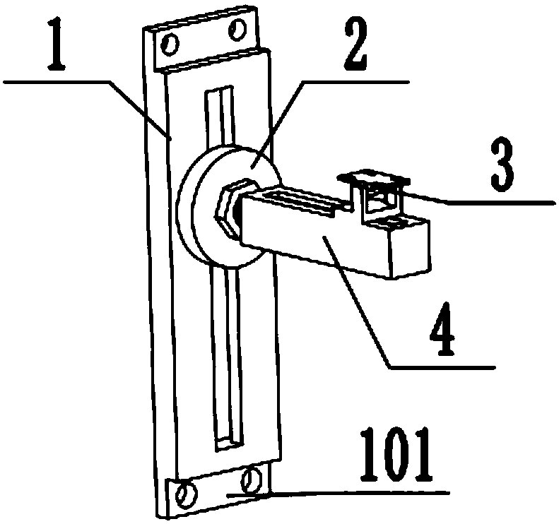
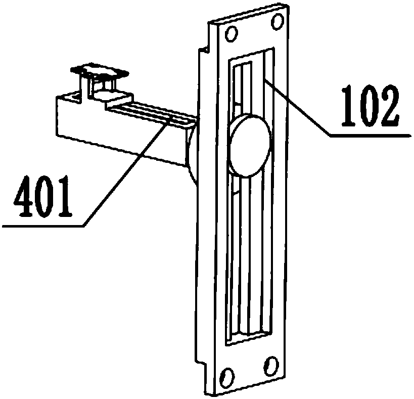
[0023] see Figure 1-5 As shown, a support frame for a monitoring camera in this embodiment is composed of a base 1, a connecting device 2 arranged on the base 1, a beam 4 connected to the connecting device 2, and a fixing device 3 for installing the camera. Composed, the middle part of the base 1 is provided with a fixed chute 102, and the fixed chute 102 is provided with a connecting device 2, and the connecting device 2 is a connecting rod fixedly connected...


PUM


Abstract

The invention discloses a monitoring camera mount which consists of a base, a connecting device, a cross beam and a fixing device; a fixed sliding groove is formed in the middle of the base; the connecting device is arranged on the fixed sliding groove; the connecting device consists of a stop block, a connecting rod fixedly connected with the stop block, and a buckling cover; the stop block is arranged in the fixed sliding groove; the connecting rod is arranged on one side of the stop block; threads are formed in one end of the connecting rod; a fastening bolt is arranged on the connecting rod; the buckling cover is fixed through the threads; one end of the connecting rod is fixedly connected with a cross beam; an adjustment groove is formed in the upper end of the cross beam; the fixingdevice is arranged on the adjustment groove; and the fixing device consists of a fixing plate, a supporting block, a sliding block, a connecting block, a rotary shaft and a fastening bolt. Rotation adjustment of the monitoring camera mount in the horizontal position can be realized in the process of carrying out vertical angle adjustment on the monitoring camera mount, the monitoring position canbe changed at any time as required, and the convenience in use is improved.

Description

technical field [0001] The invention relates to the field of camera support frames, in particular to a surveillance camera support frame Background technique [0002] Surveillance camera support frame refers to the equipment used to fix the position of security monitoring equipment. Most of the support frames currently used are brackets with fixed shapes and angles. Sometimes when in use, the angle and height cannot be adjusted to the best position, which is extremely inconvenient to use. Moreover, when changing the monitoring position in a small range, it needs to be fixed again, which is troublesome. Contents of the invention [0003] The purpose of the present invention is to provide a surveillance camera support frame to solve the problems raised in the background art above. [0004] In order to achieve the above object, the present invention provides the following technical solutions: a monitoring camera support frame, which is composed of a base, a connecting device...

Claims


Application Information

Patent Timeline
Patent Type & Authority Applications(China)
IPC IPC(8): F16M11/04F16M11/12F16M11/16F16M13/02H04N7/18
CPCF16M11/043F16M11/048F16M11/12F16M11/16F16M13/02H04N7/18
Inventor 孙笛
Owner 重庆好客信息科技有限公司
Why Eureka
Try Eureka