
Lifting device for building door and window installation assistance

A technology of building doors and windows and lifting blocks, which is applied in the direction of lifting devices, lifting frames, etc., can solve the problems of increasing the work intensity and working steps of doors and windows, affecting the construction period of doors and windows installation, accidental damage of doors and windows, etc., achieving novel design and reducing labor intensity , the effect of increasing installation efficiency

Inactive Publication Date: 2018-12-14
宁夏中科天际防雷研究院有限公司
View PDF6 Cites 12 Cited by
  • Summary
  • Abstract
  • Description
  • Claims
  • Application Information

AI Technical Summary

Problems solved by technology

[0004] In the current door and window installation process, we need to lift the installed glass doors and windows into the pre-reserved door and window frames. The usual practice is that several workers can alternately place the doors and windows in the door and window frames. This operation This method not only increases the work intensity and working steps of installing doors and windows, but also causes accidental damage during the moving process of doors and windows, which has low safety, and also seriously affects the construction period of doors and windows installation, and is not very practical.

Method used


Image

  • Lifting device for building door and window installation assistance
  • Lifting device for building door and window installation assistance
  • Lifting device for building door and window installation assistance

Examples


Embodiment Construction

[0019] It should be noted that, in the case of no conflict, the embodiments of the present invention and the features in the embodiments can be combined with each other.

[0020] In describing the present invention, it should be understood that the terms "center", "longitudinal", "transverse", "upper", "lower", "front", "rear", "left", "right", " The orientations or positional relationships indicated by "vertical", "horizontal", "top", "bottom", "inner" and "outer" are based on the orientations or positional relationships shown in the drawings, and are only for the convenience of describing the present invention and Simplified descriptions, rather than indicating or implying that the device or element referred to must have a particular orientation, be constructed and operate in a particular orientation, and thus should not be construed as limiting the invention. In addition, the terms "first", "second", etc. are used for descriptive purposes only, and should not be understood ...


PUM


Abstract

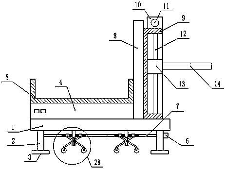
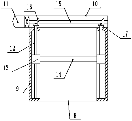
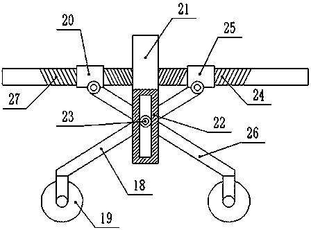
The invention discloses a lifting device for building door and window installation assistance. The lifting device for building door and window installation assistance comprises a movement seat. The two sides of the lower end of the movement seat are provided with supporting legs. The bottom ends of the supporting legs are provided with supporting mats. A rotating rod is installed between the supporting legs. The middle portions of the two ends of the rotating rods are both provided with lifting movement mechanisms. The upper end of the movement seat is connected with a storage battery group. The upper end of the storage battery group is connected with a door and window groove. The right side of the upper end of the movement seat is provided with a fixing plate. The front end and the back end of the right end of the fixing plate are both provided with guide frames. Lifting blocks are installed in the guide frames. The middle portions of the lifting blocks are provided with lead screws.The top ends of the lead screws are connected with driven gears. The upper ends of the driven gears are meshed with driving gears. The middle portions of the driving gears are provided with a transmission shaft. A lifting plate is installed between the lifting blocks. The lifting device for building door and window installation assistance achieves lifting of doors and windows without manpower, through the arranged lifting movement mechanisms, the stability in the lifting process is guaranteed, the whole device can also move, and the lifting device for building door and window installation assistance is high in safety and meets demands of door and window installation.

Description

technical field [0001] The invention relates to the technical field of auxiliary installation of building doors and windows, in particular to a lifting device for auxiliary installation of building doors and windows. Background technique [0002] Architecture is the general term for buildings and structures, and it is an artificial environment created by people using the material and technological means they have mastered, and using certain scientific laws, feng shui concepts, and aesthetic principles to meet the needs of social life. [0003] Doors and windows are divided into enclosure components or partition components according to their positions, and have different design requirements to have functions such as heat preservation, heat insulation, sound insulation, waterproof, and fire prevention. The new requirement is energy saving. The lost heat accounts for about 25% of the total heating heat consumption. The airtight requirements of doors and windows is an important...

Claims


Application Information

Patent Timeline
Patent Type & Authority Applications(China)
IPC IPC(8): B66F7/14B66F7/28
Inventor 高攀亮高筱刚黄晓红董娜
Owner 宁夏中科天际防雷研究院有限公司
Learn More