Protection device and sensor structure
A protection device and sensor technology, applied in the direction of material electrochemical variables, etc., can solve the problems of unreasonable use and short service life of electrochemical sensors
- Summary
- Abstract
- Description
- Claims
- Application Information
AI Technical Summary
Problems solved by technology
Method used
Image
Examples
Embodiment 1
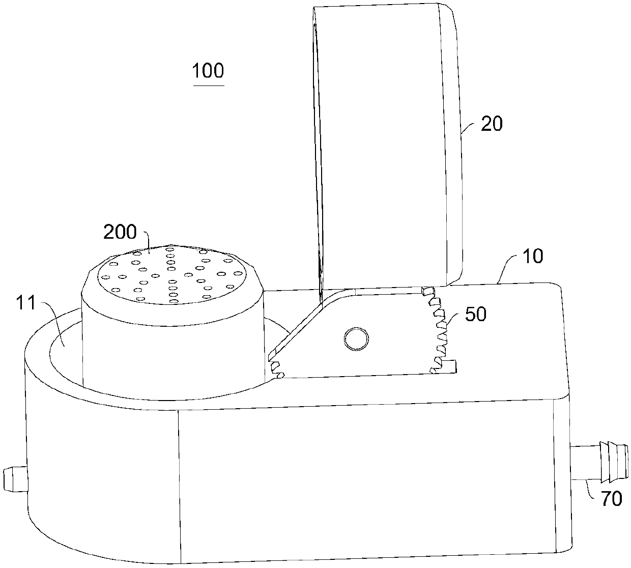
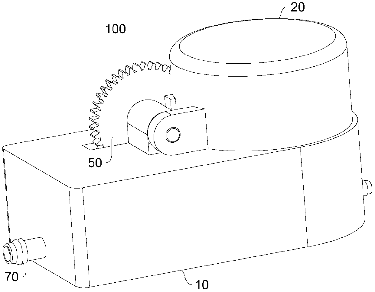
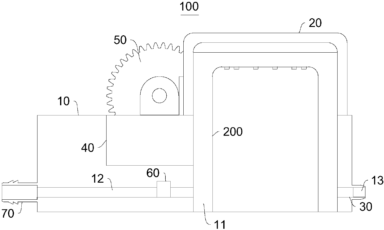
[0036] Please refer to Figure 1-Figure 3 , the present embodiment provides a protection device 100, which includes a fixed seat 10 and a movable top cover 20, the fixed seat 10 has a receiving groove 11 for accommodating the electrochemical sensor 200, and the movable top cover 20 is rotatably connected to the fixed seat 10. The fixed seat 10 is provided with an air intake passage 12 and an exhaust passage 13 communicating with the storage tank 11. The intake passage 12 is used to input the protective gas and discharge the gas in the storage tank 11 from the exhaust passage 13. The protection device 100 There is a first state in which the movable top cover 20 is away from the accommodating groove 11 and the accommodating groove 11 is opened, and a second state in which the movable top cover 20 closes the accommodating groove 11 and makes the electrochemical sensor 200 in a closed chamber.
[0037] figure 1 The protection device 100 shown in FIG. 2 is in the first state, at t...
Embodiment 2
[0061] Please refer to Figure 4 , this embodiment also provides a protection device 100, the technical solution described in embodiment 1 is also applicable to this embodiment, and the disclosed technical solution in embodiment 1 will not be described again.
[0062] Specifically, the difference between this embodiment and Embodiment 1 is that the protective device 100 further includes a gas container 80 for storing protective gas, the output part of the gas container 80 communicates with the intake passage 12, and the gas container The input part of the device 80 communicates with the connecting pipe 70.
[0063] During specific implementation, a large amount of protective gas can be filled into the gas container 80 first, so that the inside thereof is in a state of high pressure.
[0064] When inflation is required, the solenoid valve 60 is opened, and the gas container 80 instantly inflates the air intake passage 12, so that the protective gas quickly fills the containing...
Embodiment 3
[0068] This embodiment also provides a sensor structure, which includes the aforementioned protection device 100 and has all the functions of the protection device 100 .
[0069] For the structure of the protection device 100, reference may be made to Embodiment 1 or 2.
[0070] The sensor structure also includes an electrochemical sensor 200 connected to the fixing base 10 and located in the receiving groove 11 .
[0071] To sum up, the present invention provides a protection device 100, which can open the receiving tank 11 when needed, so that the electrochemical sensor 200 can be exposed to the external space for normal operation. , protecting the electrochemical sensor 200 is beneficial to improving the service life of the electrochemical sensor 200 . The structure has reasonable design, strong practicability, and huge market application potential.
PUM
 Abstract
Description
Claims
Application Information
 - R&D
- Intellectual Property
- Life Sciences
- Materials
- Tech Scout
- Unparalleled Data Quality
- Higher Quality Content
- 60% Fewer Hallucinations
Browse by: Latest US Patents, China's latest patents, Technical Efficacy Thesaurus, Application Domain, Technology Topic, Popular Technical Reports.
© 2025 PatSnap. All rights reserved.Legal|Privacy policy|Modern Slavery Act Transparency Statement|Sitemap|About US| Contact US: help@patsnap.com


